Bahnhofstrasse 18
3280 Murten / Switzerland
T+ 41 026 580 30 00
www.saia-pcd.com
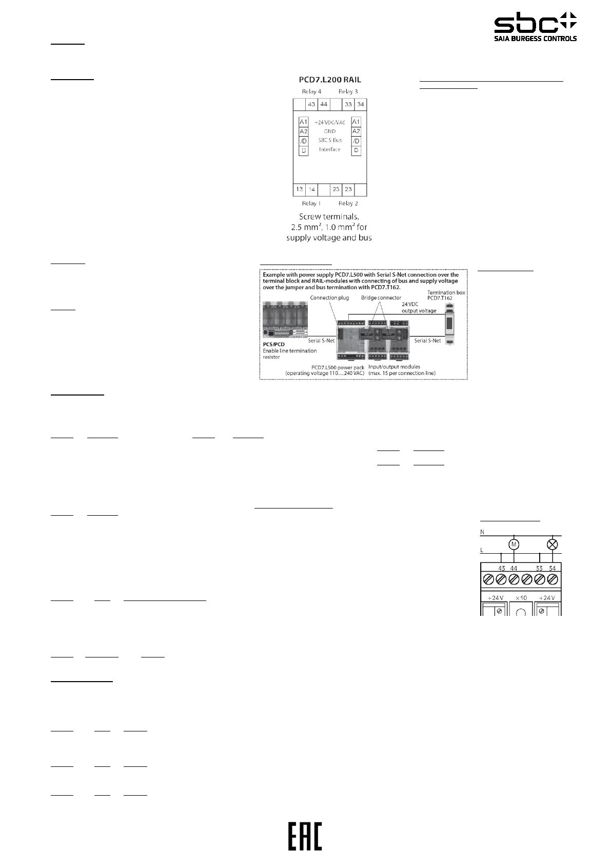
PCD7.L200 Output module with 4 relays, 250VAC/6A
Description
The RIO module was developed as a S-Bus data node for local switching tasks. Via a PLC of the type PCDx / PCS1 outputs can be set and manual/auto function monitored. Two
address switches (x1 / x10) on the front panel allow module addressing and identification. Addresses can be set between 00 and 99. Up to 100 RIO modules and a maximum of 3
PCD stations can be connected to one bus branch simultaneously. If the bus cycle time is critical, fewer than 30 slaves should be operated in one segment.
Technical data
Bus system S-Bus
Transmission rate 1200... 38400
Transmission mode Parity / Data
Bus length max. 1200 m (without repeater)
Nominal voltage UN 18VDC...32VDC / 20VAC...28VAC
Current consumption <50mADC / <80mAAC
Power consumption 1.2W / 2VA
Relative duty cycle 100 %
Reaction time 15 ms
(from receive data to
send data reaction)
Recovery time < 200ms
Operating temperature range 0°C... +55°C
Storage temperature range -25°C...+70°C
Protective wiring Reverse battery protection of service voltage
Reverse battery protection of supply and bus
EMC according to DIN EN 61000-6-2
Input state indicator Yellow LED
Function indicator Green LED for bus activity
Status indicator Red LED for bus error message
Special features Manual control level with revertive
communication via bus;
Test voltage:
Relay contact / bus 4000Veff
Output side
Number of outputs 4, electrically isolated “make” contacts
Turn-on voltage max 250VAC
Constant current 6A per relay, max. 12A
Switching frequency max. 6/min at rated load
Housing
Protection class Housing IP50 / Terminals IP20
Humidity class F (DIN 40040)
Connection cross-section 2.5 mm2 (terminals)
Plug-in terminal 1.0 mm2 (screw-type)
Mounting position any
Weight 95 g
Housing dimensions WxHxD: 35 x 70 x 74 mm
Joined without spacing After 15 modules have been joined
in sequence, the external supply voltage
must be reapplied.
Data transmission
All S-Bus instructions (level 1) are recognized. Instructions that have no function in the device are answered with <NAK>.
The module has integral, automatic baud rate and transmission mode recognition. “Output” 1 to 12 can be called together.
"Display Output / Write Output” “Display Output”
Address Information Address Information
1 0= Status relay 1 off 5 0= relay 1 switched via bus
1= Status relay 1 on 1= relay 1 switched via manual control
2 0= Status relay 2 off 6 0= relay 2 switched via bus
1= Status relay 2 on 1= relay 2 switched via manual control
3 0= Status relay 3 off 7 0= relay 3 switched via bus
1= Status relay 3 on 1= relay 3 switched via manual control
4 0= Status relay 4 off 8 0= relay 4 switched via bus
1= Status realy 4 on 1= relay 4 switched via manual control
„Display Register" Status register (register 7):
Address Information Bit 0: 1= Device recognized last transmission
5 Baud rate (plain text => kBit/s) 0= Device did not recognize last transmission
6 Module address Bit 1: 1= Last transmission was a broadcast
7 Status register 0= Last transmission was not a broadcast
8 Bus timer Bit 2: 1= Last transmission came from master
9 Current transmission mode (data / parity) 0= Last transmission came from a slave
10 Bus error counter (divided into 4 bytes) Bit 3: 1= CRC of last message was correct
0= CRC of last message was incorrect
The following registers can be called together Bit 5: 1= Device has executed an internal reset
(Display Register "x" to "y") 5 to 7 / 8 to 10 0= Device function is OK
Bit 8: 1= Internal bus to EEPROM is OK
"Write Register" 0= Internal bus not working perfectly
Address Value Baud rate setting (Baud kbit/s) Bit 9: 1= EEPROM data memory is OK
5 4 1 200 0= EEPROM data memory is faulty
5 2 400 Bit 10: 1= Baud rate uploaded from EEPROM
6 4 800 0= Baud rate is at default value (9600 Bd.)
7 9 600 Bit 12: Switch 1: 0=Automatic 1=Manuel
8 19 200 Bit 13 Switch 2: 0=Automatic 1=Manuel
9 38 400 Bit 14 Switch 3: 0=Automatic 1=Manuel
Bit 15 Switch 4: 0=Automatic 1=Manuel
Address Value range Meaning All other bits are reserved for factory tests.
8 2 <-> 20 20 <-> 200 ms
Bus timer (register 8)
The value displayed indicates how long the module waits until a telegram is complete. The time is shown in 10 ms steps (e.g.: value 20 => a time of 200 ms). The recommended
time is 100 ms, i.e. a register value of 10. If the time is reduced, modules will react faster to telegrams from the master. If there is a heavy load on the master station, a bus timer
setting that is too low may lead to lost telegrams. Times of less than 20 ms (value 2) are not permitted.
Times that reach the master station within 20 ms of the timeout will lead to lost connections. The value is stored in EEPROM and protected against voltage loss. ( Factory setting : 2)
"Write Register" "Write Output"
Address Value Meaning The write output instruction at address 255 is recognized as broadcast message.
9 1 Parity mode Automatic baud function: “Write or Display output 255” (1 = autobaud active / 0 = autobaud inactive)
2 Data mode
(factory setting) N.B:
After a power failure, the last baud rate set will be reinstalled.
Address Value Meaning
10 0 Reset of error For further information on the use of modules linked to S-Bus, including all restrictions, see documentation 26/339 E2
count register
Address Value Meaning
11 0 Bustimout deactivated
1 – 255 Time in 1 second steps -> switches the outputs to switch state defined in Output 9-12, by no bus activity within the set time will be registered
Mounting and commissioning to be conform with
current regulations:
1. Power-off the installation
2. Place module onto 35mm tophat rail and press
down to engage.
3. Strip insulation from 7mm of cable (max. single
wire 4mm2, fine strand 2.5 mm2, diameter
0.3 mm to 2.7mm), insert into binding and
tighten with a screwdriver.
Connect supply voltage and field bus to plug-in screw
terminal.
Caution!!
Plug-in terminal has max. 1.0mm2 connection
cross-section. Check correct connection of bus
lines and supply.
The relay output module is EMC proved (electro
magnetic compatibility) up to an amplitude of 2000
V. Voltage peaks caused by higher inductive loads
may initiate a module reset. In such cases it is
recommended to protect the relay contacts by an
additional RC element.
Please take care to following points
for a safety operation:
- Maximal cable length
- S-Bus member and segment
division
- Potential compensation by one
single grounding of power supply
- Termination of both network sides
- Cable shield grounding on one
side only.
"Display Output"
Adresse Information
Adresse Information
9 0= Initial State relay 1
off 5 0= Zustand Kanal 1 nach Businfo
1= Initial State relay 1
on 1 Z stand Kanal 1 nach
 Loading...