7
GB
GENERAL DESCRIPTION
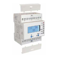
The 4 DIN instrument is suited for use in an industrial environment. Simple and extremely compact, it features an alphanumerical display
with 2 eight-character lines, 6 auxiliary LEDs and 2 buttons for display selection and keyboard programming. The machine is extremely
user-friendly and information is presented clearly on the display. It is unlikely you will need to consult instruction manual which is not
generally kept readily available at the site. When properly installed, the instrument can accept full intake flow from external CT at a
voltage of 5 to 6 A max (5 nominal). The programmed voltage is /5 A.
Voltage can be direct, max 290Vac Phase/Neutral (=230Vac+25%), or from VT
(optional). In this case it is possible to program the full scale value for
equivalent voltage at up to 400Vfn (=690Vcc), with guarantee of the displayed
values up to 25% more (500Vfn/860Vff).
For direct connection, the Vt must be the same as the rated phase/neutral
voltage, normally 231Vac. There is a “standard” range of measurements for a
high precision industrial environment. The power and power factor data are
indicated on 4 dials according to annex E in standard EN61268.
The individually resettable energies (consumed, produced and reactive) can
be
easily calculated when you need to service the system and/or test line
operation, determine zone consumption values, establish cost centres, etc.
NOTE: The instrument uses simple energy totalizing methods for purposes of
diagnostics and statistics. The instrument cannot replace an energy counter.
The following are provided according to model:
2 counters (non-resettable total and resettable partial value)
1 threshold with output on “NO” control relay (500mA/1000V), fully programmable.
1 x RS485 3kV optoinsulated programmable high speed interface with MODBUS RTU protocol.
The operating instructions, measurements and technical specifications are given below.
II
- W (production)
+ var
- cosφ /Cap
III
- W (production)
- var
- cosφ /Ind
I
+ W (consumption)
+ var
+ cosφ /Ind
IV
+ W (consumption)
- var
+ cosφ /Cap
φ
- 3 phase-to-phase voltages, direct or from VT (optional)
- 3 phase-to-neutral voltages, direct or from VT (optional)
- 3 currents from CT..../5A (1 decimal)
- Current in neutral from CT..../5A (1 decimal)
- Frequency with 2 decimals
- 3 x Active Powers with 4 dials
- Total Active Powers with 4 dials
- 3 x Reactive Powers with 4 dials
- Total Reactive Powers with 4 dials
- 3 x Apparent Powers
- Total Apparent Power
-
Power Factor of the 3 phases
- Total Power Factor
-
Total Active Energy (import) resettable parameter
- Total Active Energy ( export) resettable parameter
- Total Reactive Energy resettable parameter
- Total operation counter
- Partial operation counter
resettable parameter
- Indication of the correct voltage phase sequence
- Indication of failed voltage supply
-
RS485 3kV optoinsulated high-speed 5-speed interface
-
MODBUS RTU SLAVE PROTOCOL Full compliance
- Keypad configurable settings
- Remote configurable settings
- Remote resetting of the energies
- Remote resetting of the partial counter
- Configurable password for access to programming
- Restore factory settings
- Programming of initial page upon start-up
- Programming of CT.../5A of 5 to 6000A with step of 5A
- Programming of VT (optional) with double indication
L-L and L-N
- Programming of the analog average (V, A and P)
DISPLAYED SETTINGS
DO NOT PRESS ANY OF THE KEYS while switching on the instrument (i.e. when connecting it to the auxiliary power supply).
Otherwise you may accidentally start the calibration procedure normally carried out at the factory which, if the instrument is connected to
the system rather than to the respective calibration devices, could cause the instrument to be permanently uncalibrated. In the interest of
safety, ALWAYS WAIT FOR THE INITIAL DIAGNOSTICS TO FINISH (scanning of the LEDs) before pressing any of the keys.
“S” instruments with threshold: The threshold relay is blocked for the first ten seconds after the instrument is switched on.
The relay is “frozen” until you have finished configuring the settings.
NOTES AND OPERATING INSTRUCTIONS
When you start up the device, the firmware information page appears for a few seconds and all the LEDs switch on in order (initial diagnostics).
You will then see, for a few seconds, the page with the “title” of the measurements that will appear on the display, and the respective LED will switch
on if the page requires it to do so.
When the first measurement page appears, you can press the buttons to scroll through the available pages.
You can scroll FORWARDS by QUICKLY PRESSING the RIGHT-HAND button, or BACKWARDS by pressing the LEFT-HAND button.
Pressing
and holding the right-hand button will take you to the next page as well as allow you to program the instrumentʼs settings.
Pressing one of the 2 buttons quickly displays the “title” of the measurement page to be displayed.
OPERATION
 Loading...