Operating Instructions for LIS 101 Light Control System
3
Date: 28.02.2011
822.381 BAMA / EN
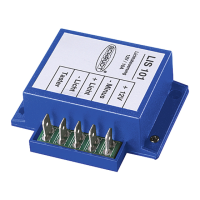
for attachment screw
Top
view
Front of device
45
12
54
24
68
1,5
2x ∅3
5x soldered--in blade terminals
straight 6.3 x 0.8
Fig. 1 Dimensional diagram of LIS 101 dimmer (dimensions in mm)
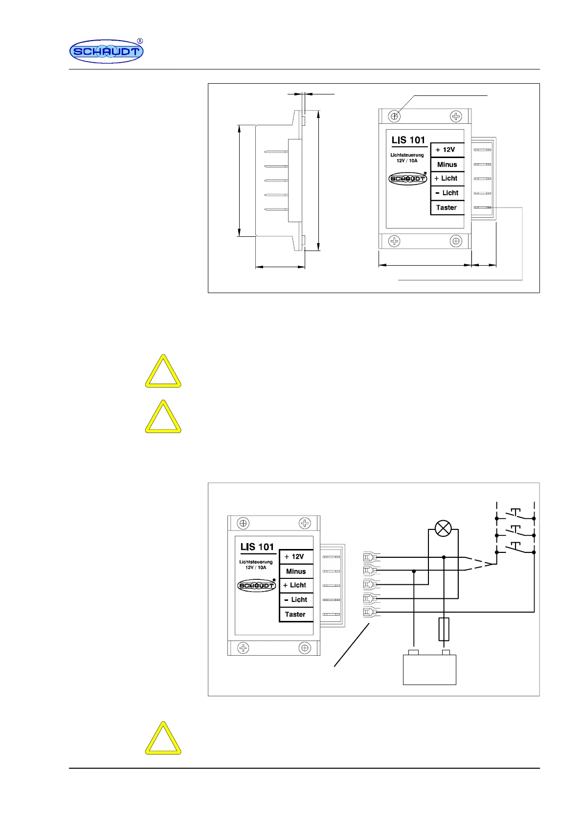
2.2 Electrical connection
Y
ATTENTION!
A fuse with a maximum rating of 10A must be inserted into the supply line to
prevent overloading.
Y
ATTENTION!
The ”Switch” input of the dimmer can be activated with either ”+12 V” or ”Mi-
nus”. A mixed connection of switches is not permitted for the connection of
multiple switches. Several switches being pressed at the same time would
lead to a short circuit.
For activation via ”+12 V”, the wire cross-section to the connector of the but-
tonmustbeselectedsufficientlylargeinlinewithfuseF1.
+--
12V s upply
LIS 101
Lighting
--
+
Light s witch
Fuse F1
max. 10A
5 blade receptacles, 6.3mm
*
* connect either to +12 V
or Minus
Fig. 1 LIS 101 dimmer circuit diagram
Y
ATTENTION!
An incorrect connection (e.g. reverse poling) may result in irreparable da-
mage to the device.
 Loading...