SCHEIBER
Bellevue, 85120 Saint-Pierre du Chemin • France
Tél : +33 (0)2 51 51 73 21 • clients@scheiber.fr • sav@scheiber.fr • www.scheiber.fr
Domotique embarquée
Embedded home automation
Marinebeam LED Lighting
660 Riverland Dr, Ste B
Charleston, SC 29412
(843) 885-8644
• A long press (1.5sec) on the L key takes you into the set-up mode.
• Output 1 (S1) ashes, briey press the switch button you want to turn
output 1 ON, then press a second time the switch button you want to
turn output 1 OFF.
Case 1 : ON/OFF with 2 buttons
Case 2 : ON/OFF with 1 button
• Each press on the L key changes the activated output. The seventh press exits the set-up mode.
• If no action is taken for 2 minutes, the module returns to normal mode.
Pairing
ON
OFF
ON/OFF
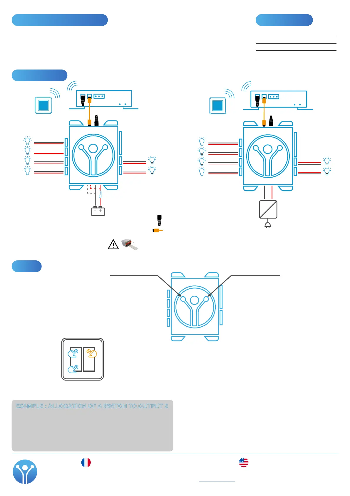
• A long press on the L key : output 1 (S1) ashes
• A second press of the L key : output 2 (S2) ashes
• Briey press the switch you want to turn output 2 ON : output 2 is ON
• Briey press the switch you want to turn output 2 OFF : output 2 ashes again
An ON switch and an OFF switch are now allocated to output 2. You can continue to
allocate more switches to the same output by pressing them or you can move on to
setting up output 3 (S3) by pressing the L key.
EXAMPLE : ALLOCATION OF A SWITCH TO OUTPUT 2
C key (clear)
To clear a set-up output or the 6 outputs
of this lighting control module
• In set-up mode, (one of the module’s outputs
ashes), a long press on the C key clears the
setup of the selected ashing output.
• In normal mode, a long press (1.5 seconds) on
the C key clears the set-up of all the outputs of
this module.
Note: It is also possible to remove one switch from
an output (without clearing the other switches
associated with that output). To do this, select the
applicable output with the L key on the module.
Then, when the output ashes, press the switch
you want to remove until the output starts ashing
again after having been o for 1 or 2 seconds.
L key (learn)
To get into set-up mode and
change the activated output
L
C
S4
S3
S2
S1
S5
S6
Wiring diagram
2.4 Ghz
120 Ω terminaison
CAN cable
S4
S3
S2
S1
S5
S6
2.4 Ghz
120 Ω terminaison
CAN cable
S4
S3
S2
S1
S5
S6
DC
AC
230V AC 8-32V DC power supply
Installation instructions
• This device must be located in a ventilated place to avoid the risk of water spatter.
• Do not install on heat-sensitive supports as carpet, PVC oor, etc...
• Imperatively install the product in a cool and dry place.
Markings used
Symbols Description
V Volt
A Ampere
Kg Kilogram
DC or Direct current
NOTE: 2.4 Ghz antenna module has been tested and found to comply with the limits for a Class B digital device, pursuant to part 15 of
the FCC Rules. These limits are designed to provide reasonable protection against harmful interference in a residential installation. This
equipment generates uses and can radiate radio frequency energy and, if not installed and used in accordance with the instructions,
may cause harmful interference to radio communications. However, there is no guarantee that interference will not occur in a particular
installation. If this equipment does cause harmful interference to radio or television reception, which can be determined by turning the
equipment o and on, the user is encouraged to try to correct the interference’s by one or more of the following measures:
- Reorient or relocate the receiving antenna.
- Increase the separation between the equipment and the receiver.
- Connect the equipment into an outlet on a circuit dierent from that to which the receiver is connected.
- Consult the dealer or an experienced radio/TV technician for help.
According §15.21 of the CFR 47- FCC part 15:
Any changes or modications to this equipment not expressly approved by the responsible party may cause, harmful interference and
void the FCC authorization to operate this equipment.
Up to 16A, you can only use one output (1-2 or 3-4).
Beyond, the power supply must be doubled (1 to 4).
Fuse 10-20A
 Loading...