The Schlage 505ULAC is a 505 Series Power Supply designed for access control applications, converting 110VAC/60Hz input to a power-limited DC output. Its primary function is to provide a stable and regulated power source, with field-selectable output voltages of either 13.8 VDC @ 1.0A or 27.6 VDC @ 1.0A nominal. This power supply is intended for operation in a controlled indoor environment.
Function Description:
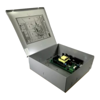
The 505ULAC features a printed circuit board (PCB) that manages power conversion and monitoring. It includes three indicator LEDs to provide real-time status updates: a red LED for DC output presence (on DC+ and DC- terminals), and two green LEDs near the supervision terminal block. One green LED indicates a connected battery, while the other signifies the presence of AC line voltage. The supervision terminal block offers connections for two relays, each with Common, N.O., and N.C. contacts, rated at 1A @ 28VDC. A key safety feature is the Emergency Interface Relay (EIR), which is standard to the power supply. The EIR's purpose is to cut power to fail-safe locks in emergency situations, ensuring compliance with safety protocols. When using the EIR relay circuit to supply power to fail-safe locks, such as electromagnetic locks, power must come from connector J6, terminals: -OUT & +OUT. The relay output reflects the condition of the EIR relay for signal or control, rated 5A @ 30VDC.
Important Technical Specifications:
- Input Voltage: 110VAC, 60Hz, 0.5 Amp
- Output Voltage: Field selectable: 13.8VDC (+/- 5%) or 27.6VDC (+/- 5%). Filtered & Regulated.
- Output Current: 1.0A @ rated voltage.
- Primary Fuse Size: 800mA, Slo-Blo, 250V, 5x20mm (F1).
- Battery Fuse Size: 2.0A, Resettable.
- Secondary Protection: Output overload protected by the regulator circuit.
- Charging Circuit: Built-in Standard.
- AC Monitor: Power Limited. Form "C" Contacts.
- Battery Monitor: Power Limited. Form "C" Contacts.
- Enclosure: 12" x 12" x 4" Approx. Steel NEMA Grade 1 with conduit knockouts and hinged cover with lock down screws.
- Color/Finish: Gray, Baked Enamel.
- Input Terminals: Barrier strip with (3) #6 screw terminals and protective cover.
- Output Terminals: Barrier strip with (2) #6 screw terminals labeled DC(+), DC(-); barrier strip with (2) #6 screw terminals labeled BAT(+), BAT(-); barrier strip (7) #6 screw terminal labeled EIR.
- Optional Stand-by Battery Pack (1): 4.0A/Hour @ 12VDC (Rechargeable, Sealed, Lead Acid, Gel Cell).
- Optional Stand-by Battery Pack (2): 8.0A/Hour @ 12VDC or 4.0A/Hour @ 24VDC (Rechargeable, Sealed, Lead Acid, Gel Cell).
- Key Lock Cover: Optional with 2 keys.
- Warranty: 1 Year Limited.
- Shipping Weight: Power Supply: 8 Pounds; Each Battery: 4 Pounds.
- Environmental Conditions: Indoor - 0°C and 49°C (32°F and 120°F) 85%, +/- 5% relative humidity.
- UL File Number: BP9350. All interconnected devices must be UL listed. Devices not evaluated by UL: CT1000, CT500, CL1000, CL500, 301+.
Usage Features:
- Installation: The 505ULAC must be installed in accordance with Article 760 of the National Electrical Code or NFPA 72, as well as all applicable local codes. It should be mounted indoors within protected premises using the provided mounting holes on the back surface of the enclosure.
- Voltage Selection: Output voltage is factory-set for 12VDC but can be changed to 24VDC by adjusting SW1 on the PCB.
- Wiring: AC power (110VAC, 50/60Hz) connects to terminals marked LINE, GROUND (symbol), and NEUTRAL. Devices to be powered connect to DC (+) and DC (-) terminals. Wiring methods must comply with the National Electrical Code (ANSI/NFPA70) and local codes. Metallic conduit should be used for branch circuit connections to maintain grounding and bonding of the enclosure. Only UL Listed and/or recognized stranded, multi-conductor, color-coded wire without splices should be used. 18AWG or larger wire is recommended for all low power connections (Battery, DC output, AC input), while 22AWG or larger is suitable for power-limited circuits (Battery Fail, AC Fail). A minimum of two spare conductors is recommended.
- Power Limited Wiring: It is crucial to keep power-limited wiring separate from non-power-limited wiring (110VAC / 60Hz Input, Battery Wires) with a minimum of 0.25" spacing.
- Stand-by Batteries: Optional for access control applications. If used, they must be lead acid or gel type. In 24VDC operation, batteries are wired in series. Without stand-by batteries, a loss of AC will result in the loss of output voltage. Batteries should be placed upright in the bottom of the enclosure and connected using provided cables. Charging time is approximately 48 hours from deep discharge.
- Tamper Switch: A tamper switch is required to be installed on the 505ULAC to monitor the enclosure for unauthorized access, complying with UL294 Section 32.1.4. This switch should be attached to a UL Listed burglar alarm system or a Listed local siren/annunciator.
- LED Diagnostics:
- DC Output (Red) ON, AC Monitor (Green) ON, Battery Monitor (Green) ON: Normal Operation.
- DC Output (Red) ON, AC Monitor (Green) ON, Battery Monitor (Green) OFF: Batteries Disconnected or Discharged.
- DC Output (Red) ON, AC Monitor (Green) OFF, Battery Monitor (Green) ON: Unit on Back-up Battery.
- DC Output (Red) OFF, AC Monitor (Green) ON, Battery Monitor (Green) OFF: DC Output Shorted.
- DC Output (Red) OFF, AC Monitor (Green) OFF, Battery Monitor (Green) OFF: Unit De-energized.
Maintenance Features:
- Annual Testing: The unit should be tested at least once a year for proper operation.
- Output Voltage Test: Under normal load conditions, the DC output voltage should be checked against the power supply voltage output specified in the Product Specifications Chart.
- Battery Test: Under normal load conditions, check that the battery is fully charged and that the specified voltage is present at all battery terminals and PCB terminals marked BAT (+) & BAT (-). This ensures there are no breaks in the battery cables.
- Fuse Replacement: For continued protection against fire hazard, replace fuse (F1) with the same type and rating (800mA, Slo-Blo, 250V). Always replace the fuse cover before re-energizing the unit.
- Battery Life: Expected battery life is 5 years. Batteries should be changed every 4 years, or less if necessary.
- Safety Warning: Always de-energize the unit prior to servicing to prevent electrical hazards.