© Allegion 2014
Printed in U.S.A.
44487023 Rev. 01/14-c
Option Board to be Plugged
into Option Connector
• See option board installation instructions
for wiring info
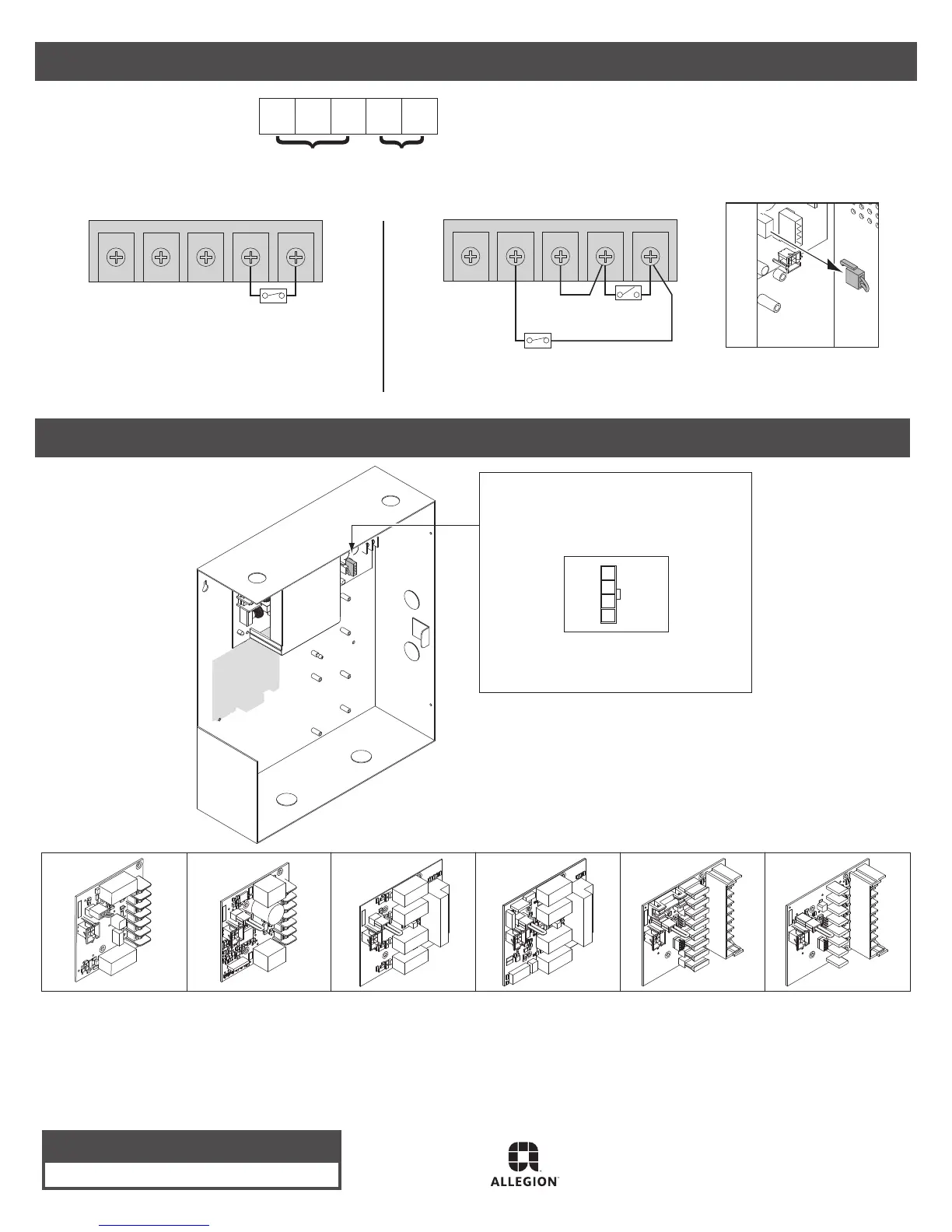
Option 1
900-2RS
(2 Relay)
900-2Q
(2 Relay w/com)
900-4R
(4 Relay)
900-4RL
(4 Relay w/logic)
900-8F
(8 Zone
Distribution-fuse)
900-8P
(8 Zone
Distribution-PTC)
Available option boards:
6 Wire 900-FA (re alarm board) if included
NC FA2FA1NOC
One 900-FA Board - Automatic Reset
NC FA2FA1NOC
One 900-FA Board - Manual Reset
Supervision Output
Contacts Shown FA Active (open)
Fire Alarm Input
NC C NO FA1 FA2
Terminal Definitions
Fire Alarm Contact
Closed = no fire
Open = fire
Manual Reset
(Temporarily close to reset)
Fire Alarm Contact
Closed = no fire
Open = fire
Note: If FA is installed on PS902:
• Verify jumper J13 is removed
• Power will be removed from
PS902 when fire alarm is active
NOTE: When installation is complete, secure enclosure door with screws (provided) or keylock
Customer Service
1-877-671-7011 www.allegion.com/us
Option Boards
Refer to appropriate instructions if any board
shown below is factory-installed
When powering (2) QEL’s with a PS902, both cannot be
activated at the same time, they must be sequenced.
Latchbolt retraction of (2) sequenced QEL’s requires more
than 1 second to complete.
For double door QEL applications with auto operators, it is
recommended to use a PS904, 906, or 914 power supply.
1.
2.
3.
Notes:
Refer to 900-FA instructions
for additional info
 Loading...