Do you have a question about the schmersal SD-I-U Series and is the answer not in the manual?
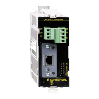
Describes the primary purpose and functionality of the UNIVERSAL gateway.
Identifies the intended audience for the operating instructions.
Details the meaning of symbols and icons used throughout the manual.
Specifies the intended applications and limitations for the product.
Provides crucial safety guidelines for installation and operation.
Highlights potential hazards and consequences of improper product use.
Outlines the manufacturer's disclaimer for damages and malfunctions.
Lists the product's order codes and variants.
Explains the main application and role of the UNIVERSAL gateway.
Presents detailed technical specifications and parameters of the device.
Covers the basic guidelines for physically installing the gateway.
Details the electrical power and connection requirements for the device.
Explains how to connect and install the serial diagnostic (SD) interface.
Describes the process of connecting the gateway to a field bus system.
Interprets the status indications provided by the device's LEDs.
Guides through the initial setup and configuration for operation.
Details how to configure settings related to the field bus communication.
Explains how to set communication parameters like baud rate.
Describes the procedure for teaching the device configuration to the gateway.
Explains an alternative teach function for fixed address ranges.
Covers how the gateway communicates with a Programmable Logic Controller (PLC).
Details the data structure and exchange for the field bus.
Explains the data format for connected SD slave devices.
Illustrates a typical wiring configuration for serial devices.
Details the PROFINET IO field bus module, including LEDs and interface.
Describes the PROFINET IRT module, its LEDs, and interface.
Covers the Ethernet/IP field bus module, its LEDs, and interface.
Explains the DeviceNet field bus module, its LEDs, and connector.
Details the CC-Link field bus module, its LEDs, and interface.
Describes the CANopen field bus module, its LEDs, and interface.
Covers the Modbus/TCP field bus module, its LEDs, and interface.
Explains the EtherCAT field bus module, its LEDs, and interface.
| Series | SD-I-U |
|---|---|
| Category | Gateway |
| Number of outputs | 4 |
| Protection class | III |
| Switching current | ≤ 500 mA |
| Connection type | M12 |