34 Copyright © 2020 Axxiom Manufacturing, Inc.
5.12 ADS System Air Outlets
On ADS Dryer Systems the air outlets are located on the after-filter (#2). There are three air outlet
ports: one primary outlet and two smaller auxiliary ports. Portable models only have one air outlet.
Refer to Section 2.8 for the outlet sizes. There are no fittings or ball valves provided with the
outlets. Any required fittings or ball valve should be provided by the user. Any valves, fittings or
hoses installed on or connected to the AirPrep System air outlet ports must have a minimum
operating pressure of 150 psi. Plug all outlet ports that are not used.
Valve, fitting, and/or hose rupture can cause serious injury or death. Do Not install or connect any
valves, fittings or hoses that are not rated for a minimum 150 psi operating pressure.
Static electric shock hazard. To minimize chance of static electrical shock to operating personnel
only use anti-static blast hose, properly electrically bond the blast nozzle, blast hose couplings, and
the equipment, and properly install an earth ground to the abrasive blaster.
5.11 Depressurize (Blowdown)
The drain ball valve (#11) is used to release all the compressed air (depressurize) from inside the
AirPrep System separator tank (#12). The AirPrep System must be depressurized for filling with
deliquescent /desiccant tablets (ADS Systems), or to perform any maintenance. To depressurize the
separator tank, turn off the air compressor and/or close the compressor’s outlet valve, then slowly
open the drain ball valve (#11) located at the bottom of the tank (see Section 6.2). The drain ball
valve should be left closed anytime the unit in not in use. If the ADS System drain ball valve is left
open deliquescent/desiccant tablets will remove moisture from air entering from outside the tank.
Airborne particles and loud noise hazards from blowdown exhaust air can cause serious injury and
loss of hearing. Wear approved eye and ear protection. Stay clear of blowdown air path. DO NOT
place hands or other body parts in the blowdown air path. Make sure no personnel are in the
blowdown air path.
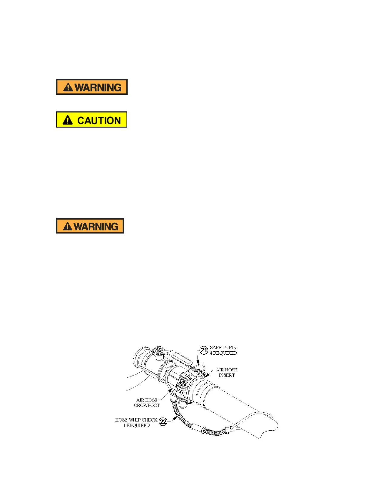
5.14 Hose Connection
Hose connections 2” and smaller can be made with 4-lug type crowfoot couplings. All air hose
couplings have pin holes that align when connected. To protect against accidental hose
disconnections safety pins (#21) must be installed through these holes. As a secondary safety
measure each hose connection should also include a hose whip check (#22) that will hold the hose
if there is an accidental disconnection. Connect one loop to each side of the connection and stretch
out as shown in Figure 5.3 below. All air hose couplings have a gasket that seals the connection and
should be replaced when air is leaking. Note: Air line connections larger than 2” must be made
using ANSI type flanges, ground joint fittings, or other approved method rated for 150psi operating
pressure.
Figure 5.2 – Hose Connection Disconnect Protection
 Loading...