Introduction
Einleitung
DCS Touch Display
DCS Touch Display
Access control
Zutrittskontrolle
Emergency exit switch
Fluchttürsicherung
Door communication
Türkommunikation
Components
Komponenten
Accessories
Zubehör
Schüco Door Control System (DCS)
C 4-12
07.2016 / 54105
Produkte und Funktionen • Products and functions
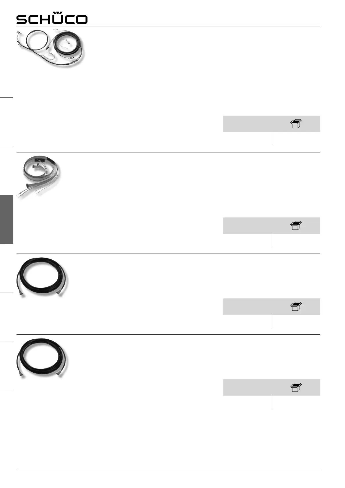
Leitungsset Fluchttürsicherung
Zu einem Kabelbaum gebündelter,
vorkonfektionierter Leitungssatz zum Anschluss
der Komponenten einer Schüco DCS
Fluchttürsicherung (Steuereinheit, Nottaster,
Schlüsselschalter, interner Schaltkontakt,
FT-Öffner sowie Ein- und Ausgänge)
● Bei der Montage im Schüco DCS Pfostenprol
bildet der Leitungssatz auch die bauseitige
elektrische Schnittstelle in der Abzweigdose
(Entfernung max. 4 m)
● Bei der Montage im Schüco DCS Flügelprol
führt er zum Leitungsübergang 263 016 /
263 017 (geeignet für Türen bis zu max. 1,4 m
Breite und 2,5 m Höhe)
Cable kit for emergency exit switch
Prepared set of cables bundled to a cable
assembly for connecting the components of a
Schüco DCS emergency exit switch (control unit,
emergency button, key-operated switch, internal
switch contact, window/door opener as well as
inputs and outputs)
● For installation in the Schüco DCS unit prole,
the set of cables also forms the electrical
interface in the junction box on site (distance:
max. 4 m)
● For installation in the Schüco DCS leaf prole,
the set of cables leads to cable link connector
263 016 / 263 017 (suitable for doors up to
max. 1.4 m in width and 2.5 m in height)
Art.-Nr.
Art. No.
263 069 1
Anschlussleitung
2. Nottaster
Leitungssatz zum parallelen Anschluss eines
zweiten Nottasters an die Schüco DCS
Fluchttürsicherung. Dieser wird benötigt sobald
die Fluchtwege zweier Raumzonen über eine
Verbindungstür in die jeweilig andere Raumzone
führen. Beide Raumzonen müssen im Normalfall
gesichert sein, im Ernstfall soll die Begehung aber
aus beiden Richtungen erfolgen können.
Connecting cable for 2nd emergency
button
Set of cables for connecting a second emergency
button to the Schüco DCS emergency exit switch
in parallel. This is required if the escape routes for
two rooms are joined to the other room by a
connecting door. Under normal circumstances, the
rooms must be secured. However, in an
emergency, access must be possible in both
directions.
Art.-Nr.
Art. No.
263 075 1
Art.-Nr.
Art. No.
263 074 1
Anschlussleitung
Nottaster – Wandmontage
12-polige Systemleitung (4,2 m) zum Anschluss
eines auf der Wand montierten Nottasters an eine
bauseitig platzierte Schüco DCS Fluchttürsiche-
rung (Steuereinheit)
Connecting cable
Emergency button – wall-mounted
12-core system cable (4.2 m) for connecting a
wall-mounted emergency button to a Schüco DCS
emergency exit switch on site (control unit)
Art.-Nr.
Art. No.
262 664 1
Anschlussleitung
Schlüsselschalter – Wandmontage
10-polige Systemleitung (4,2 m) zum Anschluss
eines auf der Wand montierten Schlüsselschalters
an eine bauseitig platzierte Schüco DCS
Fluchttürsicherung (Steuereinheit)
Connecting cable
Key-operated switch – wall-mounted
10-core system cable (4.2 m) for connecting a
wall-mounted key-operated switch to a Schüco
DCS emergency exit switch on site (control unit)
 Loading...