33
Incorrect grounding conductor /connector installation may result in electric shock risk.
Whenever connector or cable repair or replacing is needed, do not plug conductor/connector to any of the
feeding conductors. The grounding conductor - the one with green covering, with or without yellow stripes - is
t exclusively for grounding. If there is any doubt in relation to this information, or about whether the product
is adequately grounded, consult a expert electrician (one who is acquainted to electrical installation standard).
ATTENTION
TABLE 8.1
ABSORBED
POWER (W)
VOLTAGE
(V)
CURRENT
(A)
CONDUCTOR
(mm )
MAX. DIST. (m)
VOLTAGE DROP (2%)
CIRCUIT BREAKER
(A)
DR
300
127 3
1,5
35 10
25A/30mA
220 1,5 50 6
GROUND PIN
OUTLET WITH
GROUND
CONNECTION
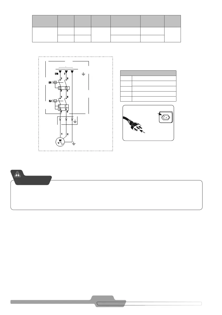
Legend (Figure 8.1)
DJ Thermo-magnetic circuit breaker
DR Residual current circuit breaker
F Phase
N Neutral
M 1 ~ Motor eléctrico monofásico
FIGURE 8.2
FIGURE 8.1 SINGLE-PHASE ELECTRICAL CONNECTION DIAGRAM
FOR HOBBY /HOME PRODUCTS
Ground
Supply voltage
Plug 2P+T
or harness
Customer’s responsability
Note: The electrical grid shall not present a voltage variation over ± 10%.
Voltage drop caused by the start must not be over 10%.
For your safety, the installation must have a grounding conductor and RD.
The Residual Differential (RD) Switch aim is to protect against electrical shock from direct and indirect contact
with electri ed parts.
The Circuit Breaker / Fuse aim is to protect the product from short circuit damage.
8. Wiring diagrams and startup keys (orientation)
The diagram in Figure 8.1 shows how the installation of the power extension, which will be used for equipment
startup, must be done by the client at the Distribution Board.