18
Ventilation of the rooms
The boiler must be installed in an adequate room in
compliance with the standards in force.
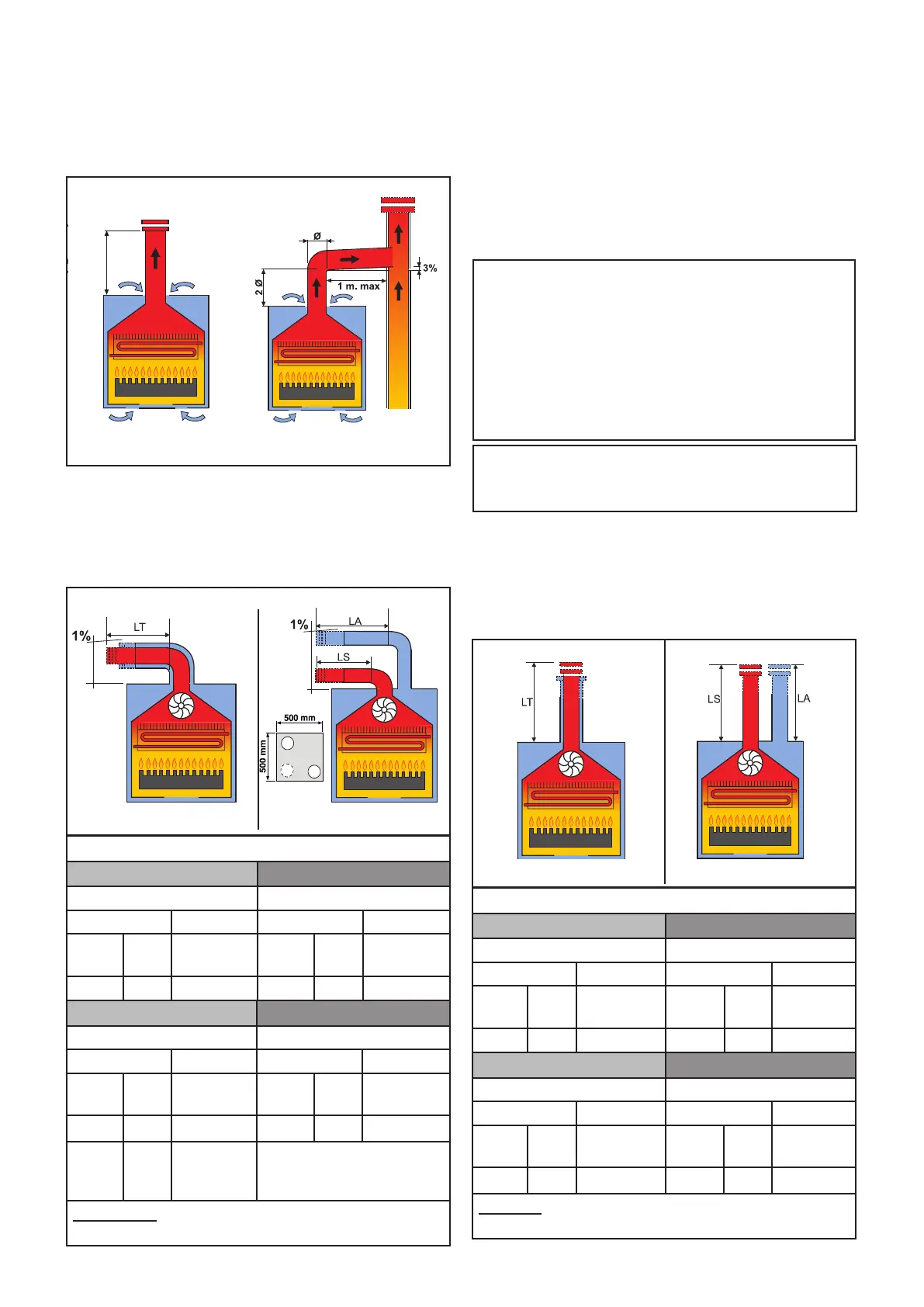
3.6 - FLUE GAS EXHAUST PIPE CONNECTION
(3%) slope towards outlet
B11bs
FOR BOILERS WITH NATURAL DRAUGHT
To connect the ue gas exhaust pipe, local and na-
tional standards must be observed
In the event the boiler is replaced, ALWAYS re-
(1%) slope towards outlet
TOTAL LENGTH (LA + LS)
COAXIAL Ø60/100 DOUBLE Ø80
COLLECTOR COLLECTOR
WITH WITHOUT WITH WITHOUT
FROM
[m]
A
[m]
UP TO
[m]
FROM
[Cps]
A
[Cps]
UP TO
[Cps]
0,5 1 3
1+1 8 + 8
40 (20A+20S)
TOTAL LENGTH (LA + LS)
COAXIALØ60/100 DOUBLE Ø80
COLLECTOR COLLECTOR
WITH WITHOUT WITH WITHOUT
FROM
[m]
A
[m]
UP TO
[m]
FROM
[Cps]
A
[Cps]
UP TO
[Cps]
1 2,5 5 3 16
40(20A+20S)
COAXIALØ80/125 DOUBLE Ø60
COLLECTOR COLLECTOR
WITH WITHOUT WITH WITHOUT
FROM
[m]
A
[m]
UP TO
[m]
FROM
[Cps]
A
[Cps]
UP TO
[Cps]
0.75
2.5
7
NA NA NA
Vertical exhaust and intake terminals directed
outside via coaxial or double pipes.
COAXIAL Ø80/125 DOUBLE Ø60
COLLECTOR COLLECTOR
WITH WITHOUT WITH WITHOUT
FROM
[m]
A
[m]
UP TO
[m]
FROM
[Cps]
A
[Cps]
UP TO
[Cps]
NA NA NA NA NA NA
Distancebetween airinlet
pipeand flue gasexhaust
pipe:min250mm-max500.
Horizontal exhaust and intake terminals directed
outside via coaxial or double pipes.
C12
C32
FOR BOILERS WITH FORCED DRAUGHT
place the ue gas pipe as well.
The boiler is type approved for the exhaust congu-
rations listed below:
The combustion air is withdrawn directly from
the room where the boiler is installed.
Said room must be ventilated in compliance with
the standards.
NOTE!
Further details in the section
‘‘Technical Information’’
CAUTION
LT total length is a reference value for the dimen-
sioning of the ducts of A (intake) and S (Exhaust).
Subtracting the values of LT reported, at values
of bends / terminals / extensions you get the
value:
if > 0 = OK - POSSIBLE conguration
if < 0 = NO - WRONG conguration
Cps = Loss coefcient specify
Value referred to curves / terminals / extensions
Ø 60 - Ø 80 wich as to subtracted from LT.