SEL-2245-4 Data Sheet Schweitzer Engineering Laboratories, Inc.
2
Figure 3 Proper Module Placement
Next, carefully rotate the module into the chassis,
making sure that the alignment tab fits into the
corresponding slot at the top of the chassis (refer to
Figure 4). Finally, press the module firmly into the
chassis and tighten the chassis retaining screw.
Figure 4 Final Module Alignment
Input Connections
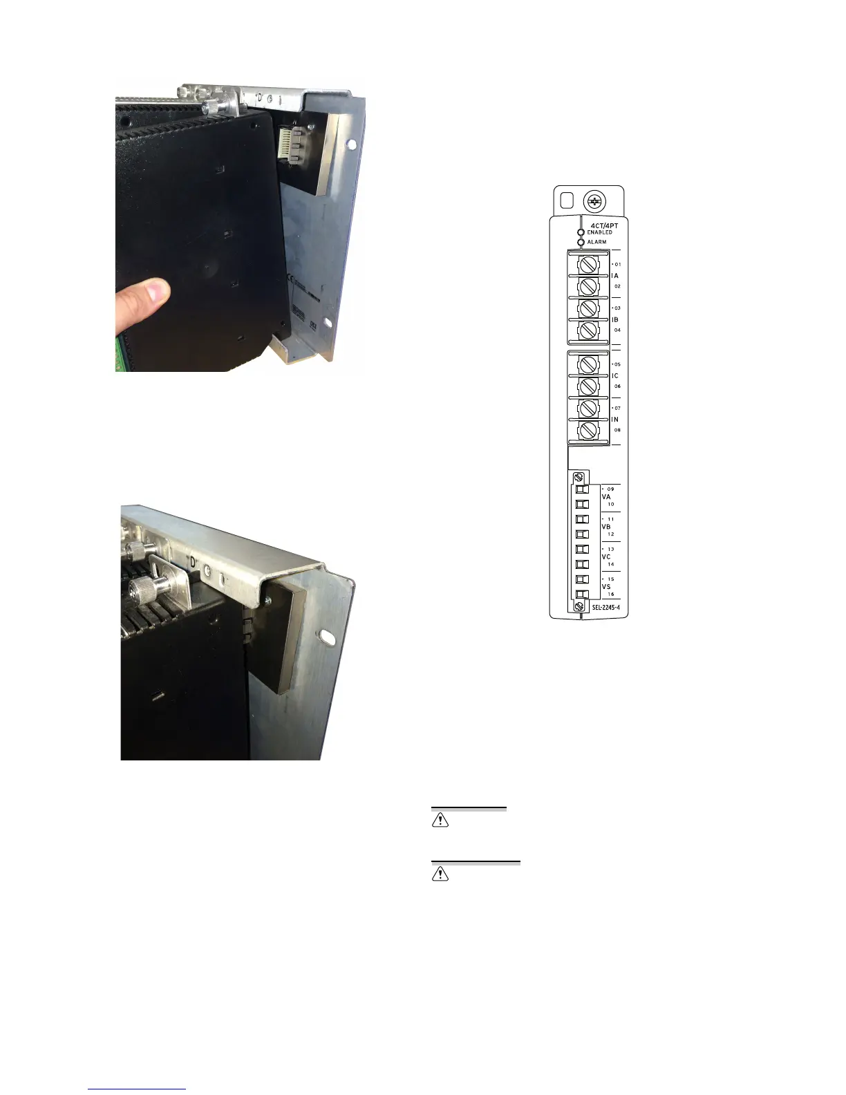
The SEL-2245-4 CT/PT analog inputs include a dot next
to the terminal number to indicate the positive
convention. Refer to Specifications for ac analog input
ratings and to Figure 5 for terminal assignments. You can
configure potential transformer (PT) inputs for 5–400 V
and current transformer (CT) inputs for 0–22 A.
Configure inputs by adding a Fieldbus I/O connection for
each module in
ACSELERATOR RTAC
®
SEL-5033
Software. See the EtherCAT
®
portion in Section 2:
Communications in the SEL-5033 Software Instruction
Manual for details.
Figure 5 CT/PT Analog Inputs
LED Indicators
The LEDs labeled ENABLED and ALARM are related to
EtherCAT network operation. The green ENABLED LED
illuminates when the module is operating normally on
the network. The ALARM LED illuminates during network
initialization or when there is a problem with the
network.
Use supply wires suitable for 60°C (140°F) above ambient. See product
or manual for ratings.
Utilisez des fils d'alimentation appropriés pour 60°C (140°F) au-dessus
ambiante. Voir le produit ou le manuel pour les valeurs nominales.
 Loading...