Home
Schweitzer Engineering Laboratories
Relays
SEL-351-5
Page 75
Schweitzer Engineering Laboratories SEL-351-5 - Page 75
696 pages
Manual
Save Page as PDF
To Next Page
To Next Page
To Previous Page
To Previous Page
Loading...
Date Code 2
0020426
Installat
ion
2-33
SEL-351-5, -6, -7 Ins
truction
Manual
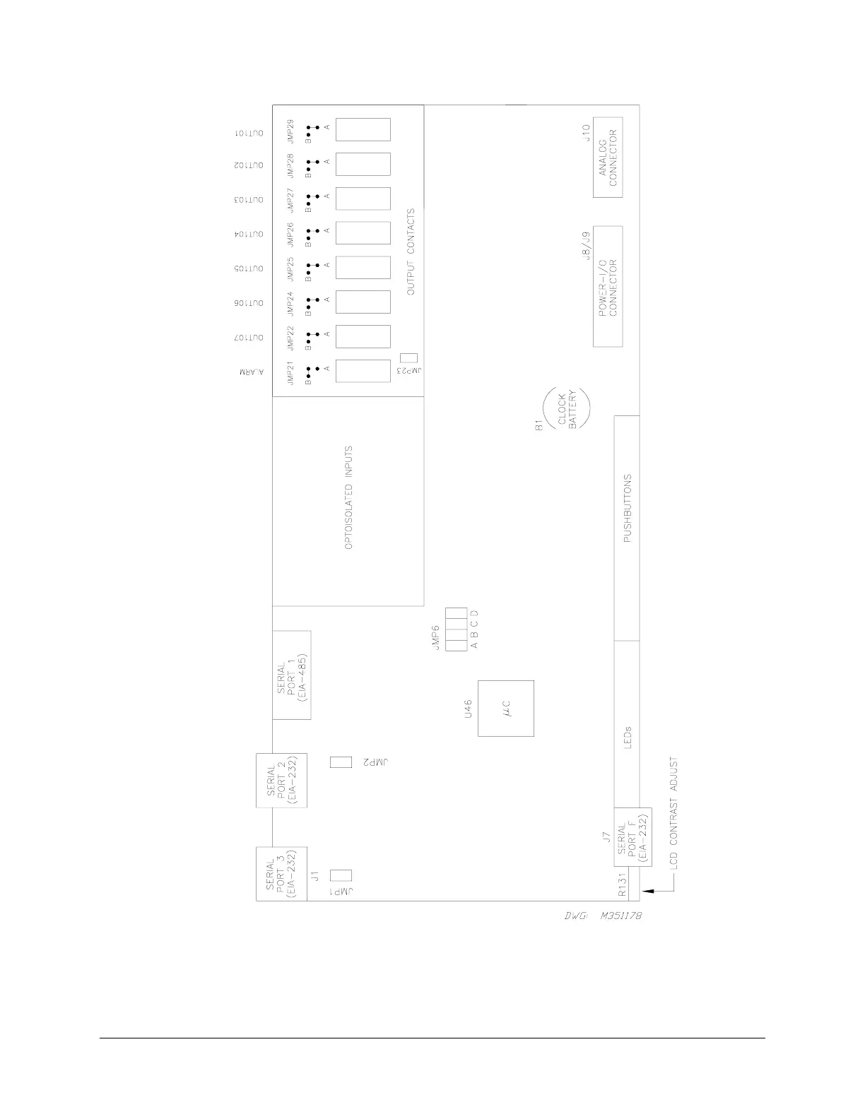
Figure 2.24:
Jumper, Connector, and
Major Compon
ent Locati
ons on the SEL-351
Relay
Main Board (Mode
ls 0351x0, 0351x1
, and 0351xY)
74
76
Table of Contents
Main Page
Table of Contents
17
Introduction and Specifications
19
Relay Models
19
Table 1.1: SEL-351 Relay Models
19
Potential Transformer Connections
20
Table 1.2: SEL-351 Firmware Versions
20
Instruction Manual Sections Overview
21
Figure 1.1: SEL-351 Relays Applied Throughout the Power System
24
Hardware Connection Features
25
Figure 1.2: SEL-351 Relay Inputs, Outputs, and Communications Ports (Models 0351X0, 0351X1, and 0351Xy; Models 0351X1 and 0351Xy Have an Extra I/O Board-See Figure 1.3 and Figure 1.4)
25
Figure 1.3: SEL-351 Relay Extra I/O Board (Model 0351Xy, Plug-In Connector Version; Main Board Shown in Figure 1.2)
26
Main Board Shown in Figure 1.2)
26
Communications Connections
28
Figure 1.5: SEL-351 Relay Communications Connections Examples
28
General Specifications
29
Instantaneous/Definite-Time Overcurrent Elements
33
Processing Specifications
33
Relay Element Pickup Ranges and Accuracies
33
Substation Battery Voltage Monitor
35
Under- and Overfrequency Elements
35
Metering Accuracy
36
Power Element Accuracy
37
Table of Contents
39
Installation
43
Relay Mounting
43
Rear-Panel Connection Diagrams
44
Making Rear-Panel Connections
48
Improvements in Connectorized
48
Models 0351Xy (Plug-In Connectors)
48
Relays (Plug-In Connectors) Result in
48
Required Equipment and General Connection Information
48
Wiring Harness
48
Chassis Ground
50
Model 0351X0
50
Model 0351Xy
50
Models 0351X0 and 0351X1
50
Models 0351X0 and 0351X1 (Screw-Terminal Blocks)
50
Output Contacts
50
Power Supply
50
High-Current Interrupting Output Contacts
51
Models 0351X1 and 0351Xy
51
Optoisolated Inputs
51
Standard Output Contacts
51
Current Transformer Inputs
52
Model 0351Xy
52
Models 0351X0 and 0351X1
52
Potential Transformer Inputs
52
Delta-Connected Voltages (Global Setting PTCONN = DELTA)
53
Determining Voltage Input Rating
53
Models 0351X0 and 0351X1
53
Wye-Connected Voltages (Global Setting PTCONN = WYE)
53
Broken-Delta VS Connection (Global Setting VSCONN = 3V0)
54
Synchronism Check VS Connection (Global Setting VSCONN = VS)
54
Polarity Check for VSCONN = 3V0
55
Wye-Connected PT Example
55
Delta-Connected PT Example
57
Serial Ports
59
Circuit Board Connections
74
Accessing the Relay Circuit Boards
74
Applications
78
Output Contact Jumpers
78
Extra Alarm" Output Contact Control Jumper
78
Password and Breaker Jumpers
79
EIA-232 Serial Port Voltage Jumpers
80
Condition of Acceptability for North American Product Safety Compliance
80
Clock Battery
81
Table of Contents
83
Instantaneous/Definite-Time Overcurrent Elements
87
Phase Instantaneous/Definite-Time Overcurrent Elements
87
Accuracy
87
Settings Ranges
87
Pickup Operation
89
Overcurrent, Voltage, Synchronism Check, Frequency, and Power Elements
87
Directional Control Option
91
Torque Control
91
Combined Single-Phase Instantaneous Overcurrent Elements
92
Pickup and Reset Time Curves
92
Phase-To-Phase Instantaneous Overcurrent Elements
94
Accuracy
94
Pickup and Reset Time Curves
94
Pickup Operation
94
Setting Range
94
Neutral Ground Instantaneous/Definite-Time Overcurrent Elements
94
Time-Overcurrent Elements
102
Synchronism-Check Elements
122
Vbase Thermal Element Block
141
Vbase Initialization
142
Vbase Tracking Range
143
SSI Reset Command
143
Power Elements (Available in Firmware Version 7)
144
Power Elements Settings
144
Power Element Time Delay Setting Considerations
145
Using Power Elements in the Relay Trip Equation
145
Accuracy
146
Single-Phase Power Elements (EPWR = 1, 2, 3, or 4)
146
Three-Phase Power Elements (EPWR = 3P1, 3P2, 3P3, or 3P4)
146
Single-Phase Power Element Calculations
147
Three-Phase Power Element Calculations
147
Power Elements Logic Operation
148
Power Elements Application-VAR Control for a Capacitor Bank
151
Settings for Three-Phase Power Elements
153
Table of Contents
155
Loss-Of-Potential Logic
159
Setting VNOM = off
160
Setting ELOP = y or Y1
160
Setting ELOP = y
160
Setting ELOP = N
161
Loss-Of-Potential, Load Encroachment, and Directional Element Logic
159
Load-Encroachment Logic
161
Settings Ranges
163
Load-Encroachment Setting Example
163
Convert Maximum Loads to Equivalent Secondary Impedances
163
Convert Power Factors to Equivalent Load Angles
164
Apply Load-Encroachment Logic to a Nondirectional Phase Time-Overcurrent
165
Use SEL-321 Relay Application Guide for the SEL-351 Relay
166
Directional Control for Neutral Ground and Residual Ground Overcurrent Elements
166
Internal Enables
168
For Low-Impedance Grounded and Ungrounded/High
171
Switch between I
171
Zero-Sequence Voltage Sources
172
Best Choice Ground Directional™ Logic
173
Directional Elements
173
Directional Element Routing
174
Loss-Of-Potential
174
Direction Forward/Reverse Logic
174
Directional Control for Negative-Sequence and Phase Overcurrent Elements
188
Internal Enables
189
Directional Elements
189
Directional Element Routing
190
Loss-Of-Potential
190
Direction Forward/Reverse Logic
190
Directional Control Settings
196
Settings Made Automatically
196
Settings
197
DIR1-Level 1 Overcurrent Element Direction Setting
197
DIR2-Level 2 Overcurrent Element Direction Setting
197
DIR3-Level 3 Overcurrent Element Direction Setting
197
DIR4-Level 4 Overcurrent Element Direction Setting
197
ORDER-Ground Directional Element Priority Setting
198
Petersen Coil Considerations for Setting ORDER
199
50P32P-Phase Directional Element Three-Phase Current Pickup
200
Z2F and Z2R Set Automatically
200
Z2F-Forward Directional Z2 Threshold
200
Z2R-Reverse Directional Z2 Threshold
200
50QFP and 50QRP Set Automatically
201
50QFP-Forward Directional Negative-Sequence Current Pickup
201
50QRP-Reverse Directional Negative-Sequence Current Pickup
201
A2 Set Automatically
202
A2-Positive-Sequence Current Restraint Factor, I
202
Loss-Of-Potential, Load Encroachment, and Directional Element Logic
213
Table of Contents
217
Trip and Target Logic
221
Trip Logic
221
Set Trip
223
Unlatch Trip
224
Other Applications for the Target Reset Function
225
Set Trip
225
Unlatch Trip
226
Additional Settings Examples
226
Unlatch Trip with 52A Circuit Breaker Auxiliary Contact
226
Unlatch Trip with 52B Circuit Breaker Auxiliary Contact
226
Program an Output Contact for Tripping
226
Three-Pole Open Logic
228
Determining Three-Pole Open Condition Without Circuit Breaker Auxiliary Contact
229
Circuit Breaker Operated Switch-Onto-Fault Logic
229
Close Bus Operated Switch-Onto-Fault Logic
229
Switch-Onto-Fault Logic Output (SOTFE)
230
Switch-Onto-Fault Trip Logic Trip Setting (TRSOTF)
230
Enable Setting ECOMM
231
Trip Setting TRCOMM
232
Trip Settings TRSOTF and TR
232
Trip Setting DTT
233
Use Existing SEL-321 Relay Application Guides for the SEL-351 Relay
233
Relays
233
Schemes
233
External Inputs
235
Use Existing SEL-321 Relay POTT Application Guide for the SEL-351 Relay
235
Logic Outputs
236
Timer Settings
236
Installation Variations
239
Variations for Permissive Underreaching Transfer Trip (PUTT) Scheme
239
External Inputs
241
Use Existing SEL-321 Relay DCUB Application Guide for the SEL-351 Relay
241
Logic Outputs
242
Timer Settings
242
Installation Variations
245
Use Existing SEL-321 Relay DCB Application Guide for the SEL-351 Relay
246
External Inputs
247
Logic Outputs
247
Timer Settings
247
Installation Variations
249
Additional Target LED Information
252
TRIP Target LED
252
INST Target LED
252
COMM Target LED
252
Another Application for the COMM Target LED
252
SOTF Target LED
253
50 Target LED
253
FAULT TYPE Target Leds
253
A, B, and C Target Leds
253
G Target LED
254
N Target LED
254
79 Target Leds
254
Target Reset/Lamp Test Front-Panel Pushbutton
254
Other Applications for the Target Reset Function
254
SEL OGIC Control Equation Setting FAULT
255
Table of Contents
257
Close and Reclose Logic
259
Close Logic
259
Set Close
260
Unlatch Close
261
Factory Settings Example
261
Set Close
262
Unlatch Close
262
Defeat the Close Logic
262
Circuit Breaker Status
262
Program an Output Contact for Closing
263
Settings and General Operation
266
For most Applications (Top of Figure 6.2)
266
For a Few, Unique Applications (Bottom of Figure 6.2 and Figure 6.3)
266
Set Reclose Supervision Logic (Bottom of Figure 6.2)
267
Unlatch Reclose Supervision Logic (Bottom of Figure 6.2)
267
Factory Settings Example
268
Additional Settings Example 1
268
Other Setting Considerations for SEL-351(1) and SEL-351(2) Relays
269
SEL-351(1) Relay
269
Additional Settings Example 2
270
Reclosing Relay
270
Reclosing Relay States and General Operation
271
Lockout State
272
Reclosing Relay States and Settings/Setting Group Changes
273
Defeat the Reclosing Relay
273
Close Logic Can Still Operate When the Reclosing Relay Is Defeated
273
Reclosing Relay Timer Settings
274
Open Interval Timers
274
Determination of Number of Reclosures (Last Shot)
275
Observe Shot Counter Operation
275
Reset Timer
275
Monitoring Open Interval and Reset Timing
276
Reclosing Relay Shot Counter
277
Ogic
277
Reclose Initiate and Reclose Initiate Supervision Settings
278
Additional Settings Example
278
Factory Settings Example
278
Respectively)
278
Other Settings Considerations
279
Drive-To-Lockout and Drive-To-Last Shot Settings
280
Factory Settings Example
280
Additional Settings Example 1
281
Additional Settings Example 2
281
Other Settings Considerations
281
Skip Shot and Stall Open Interval Timing Settings
282
Additional Settings Example 1
282
Factory Settings Example
282
Additional Settings Example 2
283
Additional Settings Example 3
283
Other Settings Considerations
284
Block Reset Timing Setting (79BRS)
284
Factory Settings Example
284
Additional Settings Example 1
285
Sequence Coordination Setting (79SEQ)
285
Additional Settings Example 2
285
Factory Settings Example
285
Section 7: Inputs, Outputs, Timers, and Other
291
Timers
292
Optoisolated Inputs
295
Input Debounce Timers
297
Input Functions
297
Factory Settings Examples
298
Input IN101
298
Input IN102
299
Local Control Switch Types
301
OFF/MOMENTARY Switch
301
ON/OFF Switch
301
ON/OFF/MOMENTARY Switch
302
Factory Settings Examples
303
Additional Local Control Switch Application Ideas
304
Local Control Switch States Retained
304
Power Loss
304
Settings Change or Active Setting Group Change
305
Section 7: Inputs, Outputs, Timers, and Other
295
Control Logic
295
Remote Control Switches
305
Remote Bit Application Ideas
306
Remote Bit States Not Retained When Power Is Lost
306
Remote Bit States Retained When Settings Changed or Active Setting Group Changed
306
Details on the Remote Control Switch MOMENTARY Position
306
Latch Control Switch Application Ideas
308
Reclosing Relay Enable/Disable Setting Example
308
Feedback Control
309
Rising Edge Operators
309
Use a Remote Bit Instead to Enable/Disable the Reclosing Relay
311
Latch Control Switch States Retained
311
Power Loss
311
Settings Change or Active Setting Group Change
311
Reset Latch Bits for Active Setting Group Change
311
Note: Make Latch Control Switch Settings with Care
312
Multiple Setting Groups
314
Active Setting Group Indication
314
Selecting the Active Setting Group
314
Ogic
314
Operation of Serial Port GROUP Command and Front-Panel GROUP Pushbutton
315
Relay Disabled Momentarily During Active Setting Group Change
316
Active Setting Group Switching Example 1
316
Start out in Setting Group 1
318
Switch Back to Setting Group 1
318
Switch to Setting Group 4
318
Selector Switch Now Rests on Position REMOTE
321
Active Setting Group Retained
322
Power Loss
322
Settings Change
322
Note: Make Active Setting Group Switching Settings with Care
323
SEL OGIC Control Equation Variables/Timers
323
Factory Settings Example
324
Additional Settings Example 1
325
Additional Settings Example 2
326
Changed
326
Output Contacts
326
Factory Settings Example
327
Operation of Output Contacts for Different Output Contact Types
327
ALARM Output Contact
327
Output Contacts OUT101 through OUT107
327
Table of Contents
347
Breaker Monitor
349
Breaker Monitor Setting Example
352
Operation of SEL OGIC ® Control Equation Breaker Monitor Initiation Setting
354
Breaker Monitor Operation Example
355
10 Percent to 25 Percent Breaker Wear
355
25 Percent to 50 Percent Breaker Wear
355
50 Percent to 100 Percent Breaker Wear
355
Percent to 10 Percent Breaker Wear
355
Breaker Monitor Output
360
Example Applications
360
View or Reset Breaker Monitor Information
360
Via Serial Port
360
Via Front Panel
361
Determination of Relay Initiated Trips and Externally Initiated Trips
361
Additional Example
361
Factory Default Setting Example
361
Breaker Monitor, Metering, and Load
349
Profile Functions
349
Introduction
349
Station DC Battery Monitor
362
Create Desired Logic for DC Under- and Overvoltage Alarming
363
DCLO < DCHI (Top of Figure 8.10)
364
DCLO > DCHI (Bottom of Figure 8.10)
365
Output Contact Type Considerations ("A" or "B")
365
Additional Application
365
View Station DC Battery Voltage
366
Via Front Panel
366
Via Serial Port
366
Analyze Station DC Battery Voltage
366
Station DC Battery Voltage Dips During Circuit Breaker Tripping
366
Station DC Battery Voltage Dips Anytime
367
Station DC Battery Voltage Dips During Circuit Breaker Closing
367
Operation of Station DC Battery Monitor When AC Voltage Is Powering the Relay
367
Demand Metering
368
Comparison of Thermal and Rolling Demand Meters
368
Thermal Demand Meter Response (EDEM = THM)
370
Time = 0 Minutes
371
Time = 5 Minutes
371
Time = 10 Minutes
372
Time = 15 Minutes
372
Demand Meter Settings
372
Demand Current Logic Output Application-Raise Pickup for Unbalance Current
375
Residual Ground Demand Current below Pickup GDEMP
376
Residual Ground Demand Current Goes above Pickup GDEMP
376
Residual Ground Demand Current Goes below Pickup GDEMP Again
376
View or Reset Demand Metering Information
377
Via Front Panel
377
Via Serial Port
377
Demand Metering Updating and Storage
377
Energy Metering
378
View or Reset Energy Metering Information
378
Via Front Panel
378
Via Serial Port
378
Energy Metering Updating and Storage
378
View or Reset Maximum/Minimum Metering Information
378
Via Front Panel
379
Load Profile Report (Available in Firmware Versions 6 and 7)
380
Determining the Size of the Load Profile Buffer
383
Clearing the Load Profile Buffer
383
Section 10: Serial Port Communications and Commands
457
Introduction
459
Irig-B
460
SEL-351 to Computer
461
SEL-351 to Modem
461
Section 10: Serial Port Communications and Commands
459
Communications Protocol
463
Hardware Protocol
463
Software Protocols
463
Mirrored Bits
465
Access Level 0
467
Access Level 1
467
Access Level B
467
Command Summary
468
Command Explanations
470
Password Requirements
471
Table of Contents
571
Introduction
573
Testing Philosophy
573
Acceptance Testing
573
Commissioning Testing
573
Maintenance Testing
574
Test Methods
577
Relay Troubleshooting
580
Inspection Procedure
580
Troubleshooting Procedure
581
Relay Calibration
581
Factory Assistance
582
Appendix F: Setting Negative-Sequence Overcurrent/Appendix G: Setting Sel Ogic Control Equations
584
BNA Message
622
SNS Message
622
Appendix E: Compressed Ascii Commands
623
Introduction
623
Appendix F: Setting Negative-Sequence Overcurrent
631
Elements
631
Coordination Example
632
Apply the Feeder Relay Negative-Sequence Overcurrent Element
634
Convert "Equivalent" Phase Overcurrent Element Settings to Negative
635
Negative-Sequence Overcurrent Element Applied at a Distribution Bus
636
Appendix G: Setting Sel Ogic Control Equations
639
Relay Word Bit Application Examples-Phase Time-Overcurrent Element
640
51Pt = 0
640
Related product manuals
SEL-351
614 pages
SEL-351-6
696 pages
SEL-351-7
696 pages
SEL-351R
620 pages
SEL-351S
636 pages
SEL-352-1
444 pages
SEL-321
396 pages
SEL-300G
714 pages
SEL-311C
748 pages
SEL-387E
578 pages
SEL-321-1
396 pages
SEL-787-3
32 pages



 To Next Page