Page 33
Page 33
RED ALARM LED ON
Too hi condensing temperature
RED ALARM LED BLINKING
Too hi evaporating temperature
YELLOW FREEZING CYCLE ON
Unit in freezing cycle mode
YELLOW FREEZING LED AND RED ALARM
LED ON
Condenser sensor out of order
YELLOW FREEZING LED AND RED ALARM
LED BLINKING
Evaporator sensor out of order
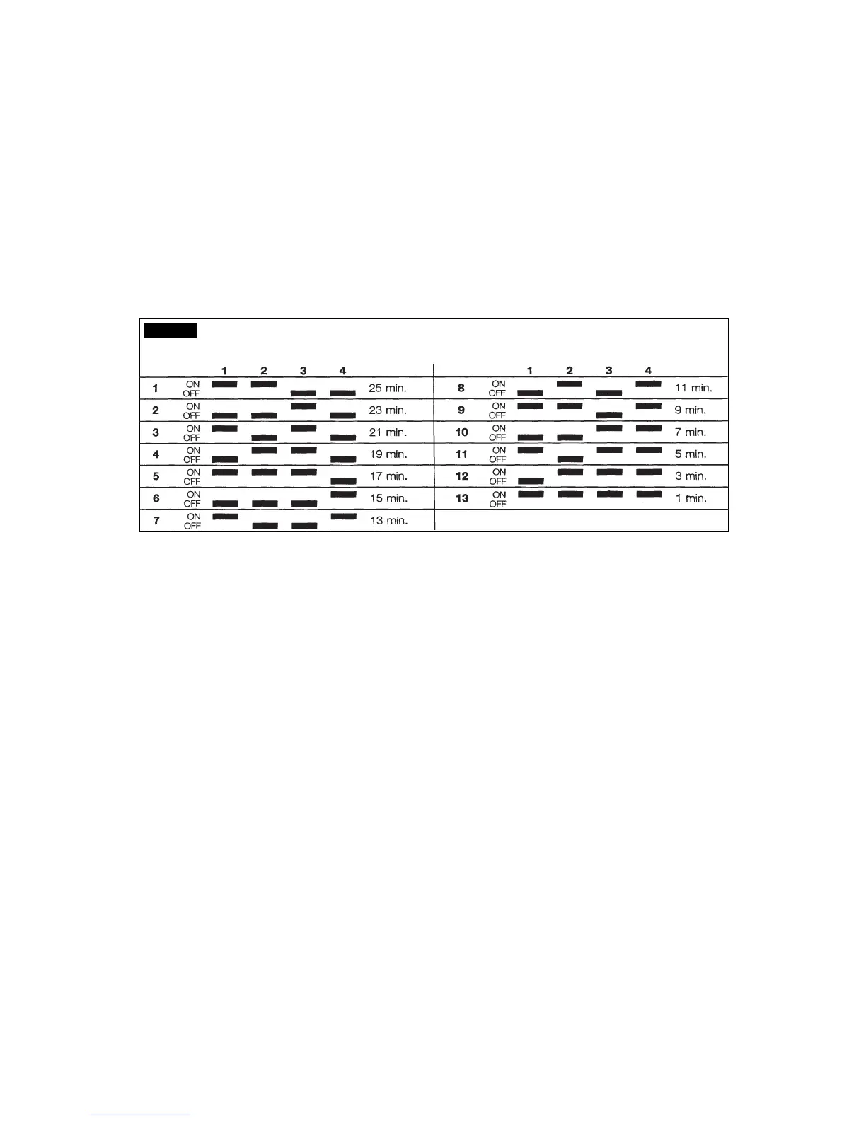
G. DIP SWITCH
The P.C.BOARD which controls the entire
operation of the ice maker, has a DIP SWITCH
with ten switching keys which allow to set up
the micro processor program in order to extend
or to shorten the length of freezing cycle in
relation to the different model and versions of ice
machines.
The DIP SWITCH first four keys setting
determines the length of the 2nd phase of
freezing cycle (controlled by the electronic
timer) as detailed in the table B.
The DIP SWITCH keys 5 & 6 setting determines
the length of the defrost cycle according to the
size of the cubes (Large or Medium) as per the
following setting:
ON ON : A
ON OFF : B
OFF OFF : C
OFF ON : D
It is not possible to modify the length of the
defrost cycle (factory setting).
LENGTH OF HARVEST CYCLE
ACCORDING TO THE TIME TO DROP THE
EVAP. TEMPERATURE FROM 0ºC TO -15ºC
LENGTH PROGRAMS
HARVEST
CYCLE
ABC D
180” U p t o 6’30” *** Up to 9’30” Up to 3’30”
165” 6’30”-7’ Up to 3’ 9’30”-10’ 3’30”-4’
150” 7’-8’ 3’-3’15’ 10’-11’ 4’-4’30”
135” 8’-9’ 3’15”-3’30” 11’-12’ 4’30”-5’
120” 9’-10’30” 3’30”-4’30” 12’-13’30” 5’-5’30”
105” 10’30”-12’ 4’30”-6’ 13’30”-15’ 5’30”-6’
90” >12’ >6’ >15’ >6’
The 7th D.S. key is not used in this release of the
P.C. BOARD.
The 8th key allows the operation of the water
pump even during the defrost cycle, as required
when it is necessary to drain out the remaining
water from the sump.
The 9th key is used to supply power to the water
pump for the first 15 seconds of the defrost cycle
- position OFF - or for the first 30 seconds -
position ON.
The 10th key is used to modify the CUT-OUT
condensing temperature from 70°C (160°F) for
the water cooled versions - ON position - to 60°C
(140°F) - OFF position - for the air cooled
versions.
H. WATER SPRAY SYSTEM
Through its nozzles, the water pumped, is sprayed
in each individual cup to be frozen into ice.
It consists of one spray tube wheve are located
several spray nozzles.
I. WATER PUMP
The water pump operates continually throughout
the freezing cycle and on the first 15 or 30
seconds of the defrost cycle so to such the
remaining water from the sump tank (reach in
mineral salts) and drain it out.
During the freezing cycle the pump primes the
water from the sump to the spray system and
through the spray nozzles sprays it into the
inverted cup molds to be frozen into crystal clear
ice cubes.
It is recommended that the pump motor bearings
be checked at least every six months.
J. WATER INLET SOLENOID VALVE -
3/4 MALE FITTING
(Water cooled version)
A special water inlet solenoid valve with one inlet
and two outles (one for condenser and the second
for the production of ice) is used on water cooled
version.
LENGTH OF TIMED PORTION OF FREEZING CYCLE ACCORDING TO THE
DIP SWITCH SETTING COMBINATIONS
TAB. B