Do you have a question about the Scotsman MXG 328 A/W and is the answer not in the manual?
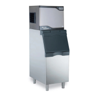
Steps for placing the ice maker on the bin and preparing I/R sensor/chute.
Procedure for routing the I/R sensor through the unit's base gasket.
Instructions to fix the IR sensor using supplied screws to its bracket.
Fixing the IR bracket at the ice chute discharge area with a screw.
Re-installing the ice chute, ensuring proper hook rim point attachment.
Verifying data plate for voltage and ensuring a solid earth wire connection.
Specifies required ambient/water temperatures and pressures for operation.
Details minimum clearance needed for connections and optimal air routing.
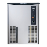
Visual representation of air flow for specific MXG models (328-438).
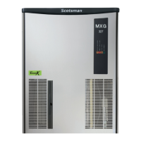
Visual representation of air flow for the MXG 638 model.
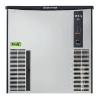
Visual representation of air flow for the MXG 938 model.
Instructions on leveling the unit using its adjustable legs.
Guidance on installing the electrical supply and appropriate plug.
Steps for connecting the water inlet and drain lines correctly.
Diagram showing typical installation for air-cooled versions.
Details on the two separate 3/4” male thread water inlet fittings.
Connecting the second drain hose to the water regulating valve.
Diagram showing typical installation for water-cooled versions.
Steps to open the water tap and switch on the electrical supply.
Location and function of the front panel master push switch.
Procedure for starting the machine using the green push button.
Information on factory start-up delay and Jumper 3 settings.
Describes the automatic water filling phase after the start-up delay.
Identifies the PC Board as an energized component during water filling.
Identifies the water inlet solenoid valve.
Identifies the water drain valve.
Identifies the hot gas solenoid valve.
Traces water flow through the inlet valve and flow control orifice.
Explains how water flows onto the evaporator platen via holes.
Describes water collection in the sump and the overflow's role.
Lists the compressor as an operating component during the freezing cycle.
Lists the water pump as an operating component during the freezing cycle.
Lists the fan motor for air-cooled versions during the freezing cycle.
Lists the contactor as an operating component during the freezing cycle.
Explains fan motor control via condenser temperature sensor.
Identifies the 'Power' LED on the PC Board.
Identifies the 'Freezing' LED on the PC Board.
Details water circulation into the evaporator molds.
Describes refrigerant flow in the evaporator serpentine.
Points out the evaporator sensor location.
Notes the evaporator serpentine temperature drop to 0°C after 5 mins.
Indicates a blinking red LED on the PC Board.
Notes the evaporator serpentine temperature drop to -15°C after 10 mins.