ASSEMBLY
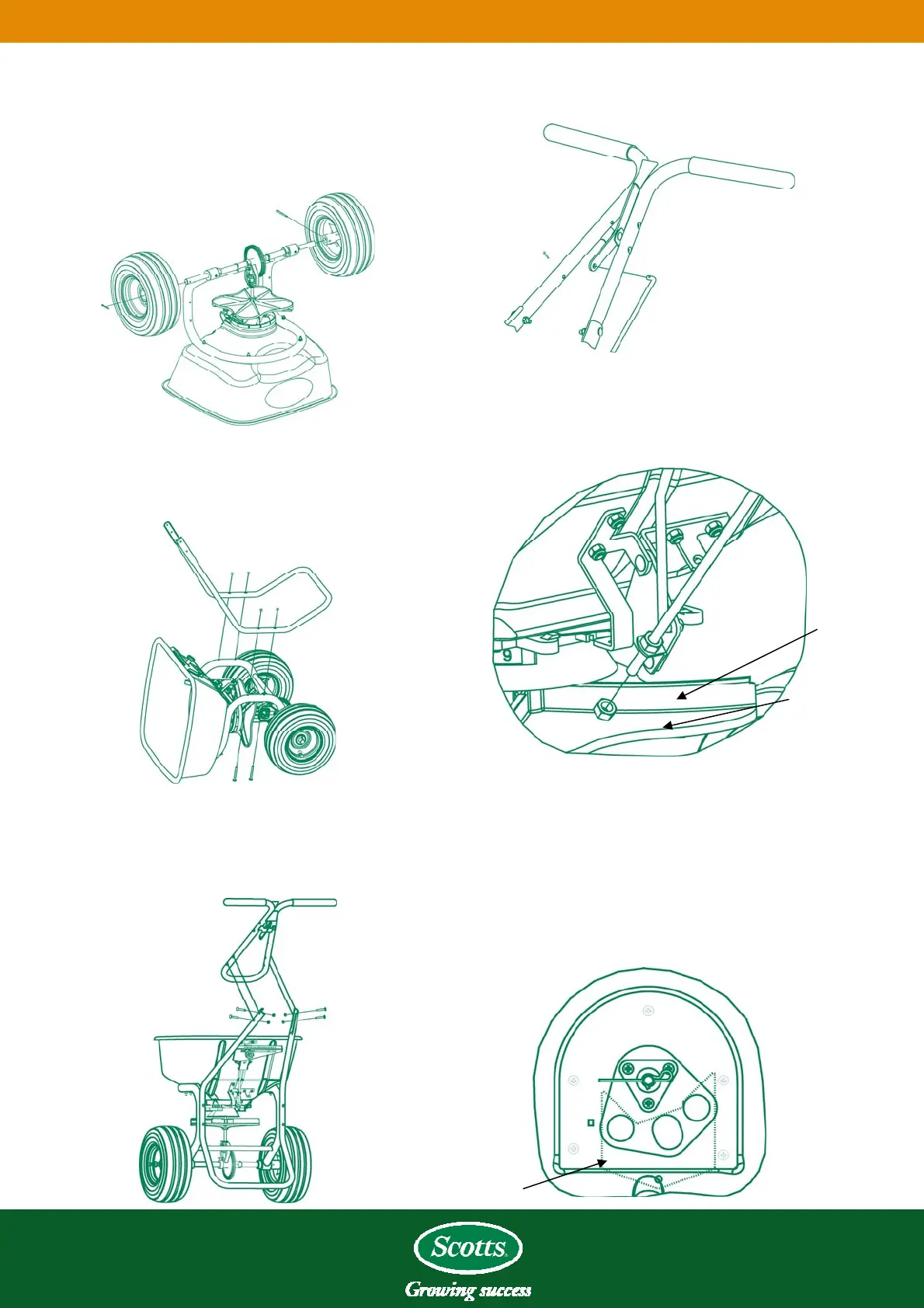
4. Place the
bent end of the main shutoff connecting
rod through the hole in the lever and secure it with a
cotter pin on the right side.
1. Turn the spreader upside-down. Place the wheels
on t
he axle with the longer portion of the hubs facing
inward. Secure the drive wheel A (right side) to the
axle using the 3/16” cotter pin. Attach the idler wheel
B (left side) to the axle. Then insert the 1/8” cotter
pin through the axle and secure.
B
5. Thr
ead one hex nut onto the lower end of the main
shutoff control rod until it stops. Insert the rod
through the pivot lever arm, as shown, and thread the
second nut up to the pivot lever arm; do not tighten.
2. Place t
he spreader on its front side and attach the
rest to the frame using four 2 1/2” Phillips screws
and four lock nuts.
Top Nut
Piv
ot Lever
Arm
3. Retur
n the spreader to the upright position and
attach the handle to the rest with four 11/2” carriage
bolts and four lock nuts. Be sure that the main
shutoff lever is facing up.
6. Pull the main shutoff lever to the closed position and
look inside
to see if the port holes are closed. If not,
adjust the top nut down in small increments and check
for closure. CAUTION - DO NOT ADJUST THE
TOP NUT TOO FAR DOWN TO PREVENT
BINDING THE MECHANISM. When the ports
close completely, bring the bottom nut up and tighten
both.
Main Shutoff Plate
Closed Position