TB-9083 Page 2 of 3
© 2020 DESCO INDUSTRIES INC
Employee Owned
SCS - 926 JR Industrial Drive, Sanford, NC 27332
East: (919) 718-0000 | West: (909) 627-9634 • Website: StaticControl.com
2. Select “1.5M LOW” with the operator rotary switch.
The monitor’s green OK 1 LED should illuminate,
and the yellow L LED should blink. The audible
alarm should not sound.
3. Select “1.5M PASS” with the operator rotary switch.
The monitor’s green OK 1 LED should illuminate,
and its audible alarm should not sound.
4. Select either “10M PASS” or “35M PASS”,
whichever one is appropriate, with the operator
rotary switch. The monitor’s green OK 1 LED should
illuminate, and its audible alarm should not sound.
5. Select either “10M HIGH” or “35M HIGH”, whichever
one is appropriate, with the operator rotary switch.
The monitor’s red H LED should illuminate, and its
audible alarm should sound continuously.
6. Repeat steps 1-5 for jack #2 on the operator
remote. The audible alarm will chirp when jack #2
fails high.
Testing the Mat Circuit
Equipment Needed
• Resistance Decade Box
(1 megohm to 5 megohm range, ±1% tolerance)
• 2 Test Leads for the Resistance Decade Box
• 1 Alligator Clip
1. Connect the two test leads to the resistance decade
box.
2. Connect one of the test leads to equipment ground.
3. Disconnect the 724 Workstation Monitor’s mat
monitor cord from its worksurface mat. The mat LED
should illuminate red, and the audible alarm should
sound.
4. Use an alligator clip to connect the second test lead
from the resistance decade box to the metal snap on
the mat monitor cord.
5. Set the resistance decade box to the values shown
in the table below. The 724 Workstation Monitor’s
Mat LED and audible alarm should behave as
described in the table.
Load
Resistance
Mat LED Audible
Alarm
3.1 megohms O O
4.3 megohms On On
725 Portable Wrist Strap Monitor
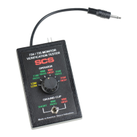
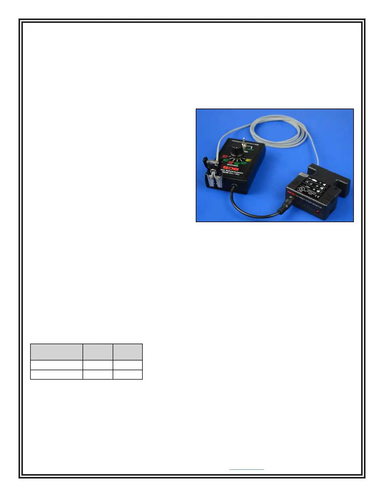
1. Select “SHORT” with the Verification Tester’s
ground clip toggle switch.
2. Connect the monitor’s ground clip to the pins
located at the top of the Verification Tester. Each
conductor on the ground clip should only touch one
pin.
3. Insert the Verification Tester’s stereo plug into the
monitor’s operator jack.
Figure 4. Using the Verication Tester with the 725
Portable Wrist Strap Monitor
4. Select “35M PASS” with the operator rotary switch.
The monitor’s LED should not illuminate, and its
audible alarm should not sound.
5. Select “35M HIGH” with the operator rotary switch.
The monitor’s LED should blink, and its audible
alarm should sound.
6. Select “35M PASS” with the operator rotary switch,
and select “10M PASS” with the ground clip toggle
switch. The monitor’s LED should not illuminate,
and its audible alarm should not sound.
7. Select “10M HIGH” with the ground clip toggle
switch. The monitor’s LED should illuminate, and its
audible alarm should sound continuously.
 Loading...