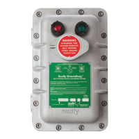
Self-Proving Vehicle Grounding Verication System
Initial System Checkout
Page 11.
4.1 General
(Refer to Figure 1.2 for Terminal Block & Fuse Locations)
Note: All Tests are done with line power applied to the ST-47.
4.2 Models Without Bypass Switch (ST-47- 115 or 240 EL)
Remove all wiring from the I.S. Terminal Strip TB2. You may check operation of the Groundhog by
physically shorting together terminals 1 and 2 on TB2 using a jumper wire. When this test is
performed, the Permit light should illuminate and Permit contacts (TB1 terminals 3 and 4) should
close. When the ST-47 is in the permissive mode any connected devices should activate. If the
connected device does not activate, consult the Troubleshooting section of this manual.
4.3 Models With Bypass Switch (ST-47- 115 or 240 ELK)
Place the Bypass switch in the AUTO position (center position). Remove all wiring from the I.S.
Terminal Strip TB2. You may check operation of the Groundhog by physically shorting together
intrinsically safe terminals 1 and 2 on TB2. When the test is performed, the permit light should
illuminate and the Permit contacts (TB1 terminals 4 and 5) should close. Place switch BYPASS
position (to the right). When the switch is in the Bypass position, power is removed from the ST-47
electronics and the front cover status lamps. Verify that the red and green status lamps are
extinguished and contacts TB1 terminals 4 and 5 are shorted. When the ST-47 is in the permissive
mode any connected devices should activate. If the connected device does not activate consult the
Troubleshooting section of this manual.
4.4 Models With Deadman Feature (ST-47- 115 or 240 EL(K)/D)
4.4.1 Models with Bypass Switch
To test the operation of the deadman switch, the ST-47 must be powered by the line voltage and
the Bypass switch in the AUTO position. When the ST-47 is not connected to a vehicle, rail car,
etc., the Red lamp on the front cover is lit. Connect the plug and cable or clamp to the vehicle to be
grounded. If the vehicle ground is veried the Green lamp on the front cover lights. If the Green
lamp does not light refer to previous sections 4.1 to 4.3.
Operate the deadman handle, the external device connected to the ST-47 permissive output will
activate. When the ST-47 is in the permissive mode any connected devices should activate. If the
connected device does not activate consult the Troubleshooting section of this manual.
4.4.2 Models without Bypass Switch
Perform the test as in paragraph 4.2 by applying power to the ST-47. Applying power is equivalent
to placing the Bypass switch in the AUTO position. When the ST-47 is in the permissive mode any
contact devices should activate. If the connected device does not activate consult the
Troubleshooting section of this manual.
CAUTION
Hazardous Voltages are Present Inside the ST-47 Explosion Proof
Housing. When Working Inside the ST-47 Enclosure Avoid Contact with
the TB1 Terminal Strip at the Top of the Housing

 Loading...