2.7.4 Connection and choice of cables
For all connections, use flexible, strong rubber-sheathed cables which comply with standard IEC 60245-4 or equivalent cables, and
ensure that these are kept in perfect condition. Only use one class I electrical device per socket and connect up equipment using a
cable equipped with a PE protective conductor (green/yellow); this protective conductor is not required for class II equipment.
Adhere to the cross sections and lengths recommended in this table during installation or when using electrical extensions.
Generating set type:
Single phase Three-phase
Generating set socket type:
10 A 16 A 32 A 10 A 16 A
Recommended cable cross section:
mm² AWG mm² AWG mm² AWG mm² AWG mm² AWG
Length of
cable used
0 to 50 m 4 10 6 9 10 7 1.5 14 2.5 12
51 to 100 m 10 7 10 7 25 3 2.5 12 4 10
101 to 150 m* 10 7 16 5 35 2 4 10 6 9
*This cable length is the maximum permitted length, and must not be exceeded.
Installation method = cables on raceway or non-drilled tablet/Permitted drop in voltage = 5%/Multi-core conductors/Cable type PVC
70°C (e.g. H07RNF)/Ambient temperature =30°C.
2.8 Risks during handling operations, use and maintenance
For safety reasons, all operations must be carried out by staff with the necessary skills and using suitable equipment. Maintenance
must be carried out regularly and properly using only original or equivalent parts. Gloves must be worn.
Safety guidelines for handling petroleum products:
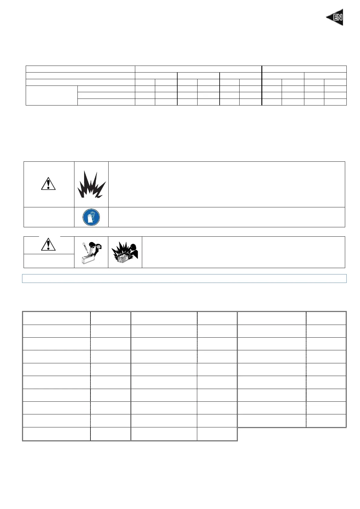
RISK OF EXPLOSION
Respect the local regulations in force concerning the handling of petroleum products.
Filling should be carried out with the engine switched off and cold. Smoking, using a
naked flame or producing sparks are forbidden while the fuel tank is being filled. After
filling, always check that the tank's filler cap is properly tightened. Clean any traces of
fuel with a clean cloth and wait until the vapours have dispersed before starting the
generating set.
DANGER
The fluids used by generating sets, such as oils and fuels, are dangerous products.
Never ingest them. Avoid prolonged or repeated contact with the skin.
Safety guidelines for handling batteries:
RISK OF POISONING OR EXPLOSION
Follow the battery manufacturer's recommendations. Use insulated tools
only. Never use sulphuric acid or acid water to top up the electrolyte level.
Never leave the battery close to a flame or fire. Always ensure adequate
ventilation during charging.
DANGER
3 Getting started with the generating set
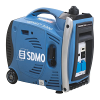
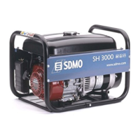
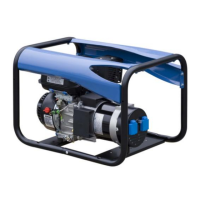
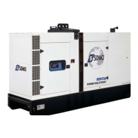
3.1 Key to illustrations
The cover illustrations can be used to identify the various components of the generating set. The procedures in the manual refer to
these illustrations using letters and numbers as identifiers, for example, (A1) refers to the number 1 on figure A.
Oil dipstick/filler plug A1-B2 Electrical sockets A10 Foam element D3
Filler neck B3 Oil drain screw A11-B1 Spark arrester A17-E2
Fuel level indicator A2 Fuel filter A12
Spark arrester mounting
bolt
E1
Fuel tank cap A3 Fuel filter mounting clips A13
Exhaust silencer
protection
E3
Screen filter A4 Side panels A14 Fuel drain screw C5
Fuel tap A5 Sediment bowl A15-C3
Spark plug
A18-F2
Choke A6 Sediment bowl cover C1
Spark plug cap F1
Switch A7 Seal C2
Circuit breakers A19
Starter-recoil reel handle A8 Air filter A16
Earth connection A20
Operating light A9 Air filter cover D2
 Loading...