Section 3. Getting started with the generating set
3.1 Key to illustrations
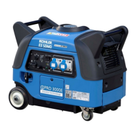
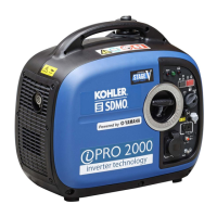
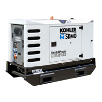
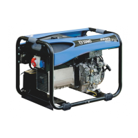
The cover illustrations can be used to identify the various components of the unit. The procedures in the manual refer to these
illustrations using letters and numbers as identifiers: "A1" refers to the number 1 on figure A.
Starter-recoil reel handle
Air filter cover fasteners
Electric sockets (alternating
current)
12 V socket (direct current)
Circuit breaker for 12V socket
Spark plug access cover screws
Exhaust silencer cover screw
Oil cut-out warning light
Exhaust silencer grille screw
Economic idle speed (Hare-
Tortoise)
* Source inverter, battery charger, etc.
3.2 Initial commissioning
On taking delivery and commissioning the unit:
1. Check that it is complete and not damaged in any way.
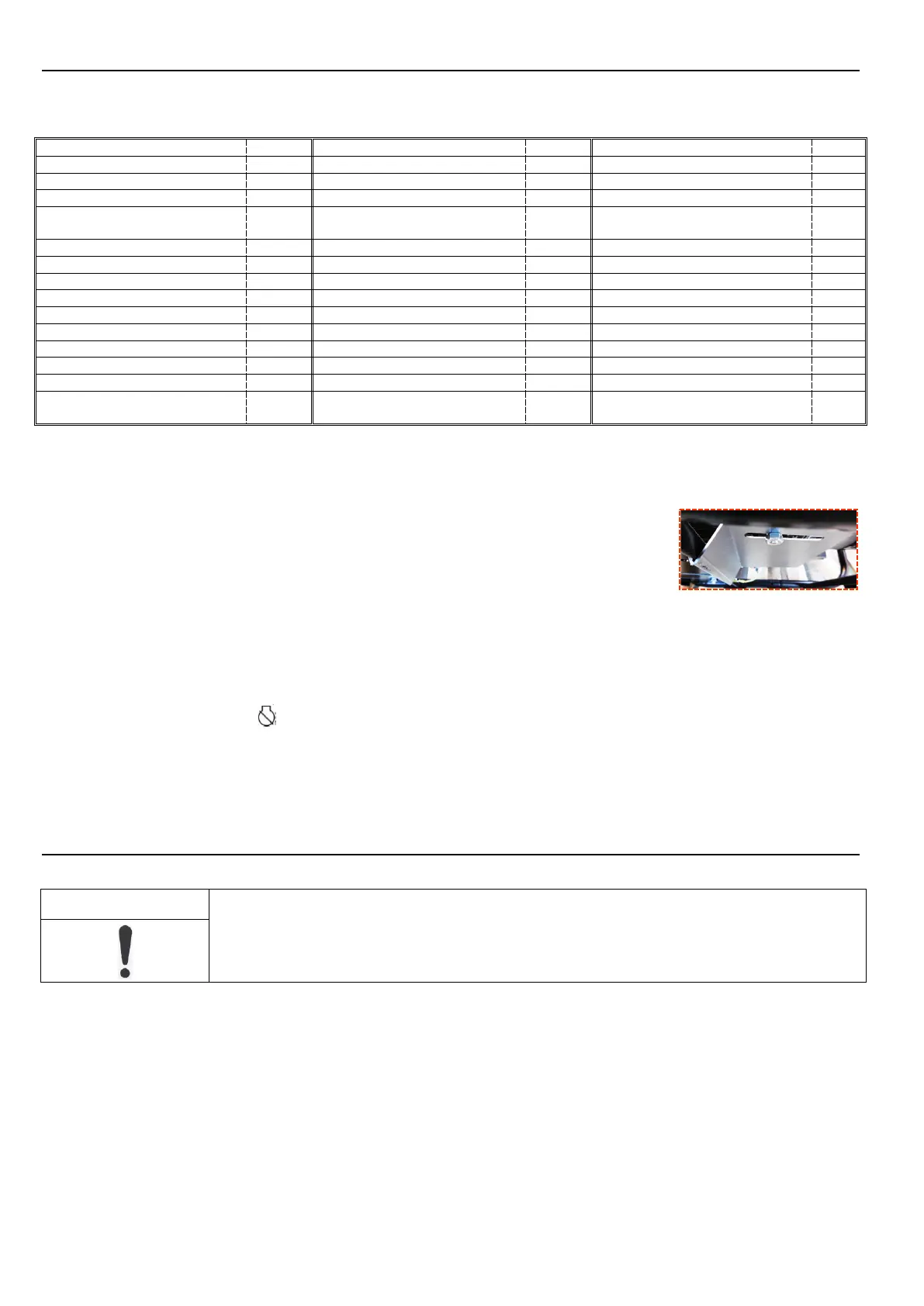
2. If the unit is fitted with a transport bracket, remove it.
The transport bracket is a metal plate located underneath the engine, close to the earth terminal.
Although useful for transportation, it will prevent optimum operation of the unit (noise, vibration).
To remove it: lift the unit slightly and place it on a block then remove the nut (1) and the clamp (2).
3. Check the oil and fuel levels and top them up if necessary.
4. If necessary, connect the battery, starting with the positive terminal.
Observe the polarity of the battery terminals when connecting it: as this could cause serious damage to the electrical equipment.
Some units require a running-in period. Contact your nearest agent for more information.
3.3 Installing the battery
1. Set the switch (A7) to the position.
2. To access the battery (A6), remove the nuts (A4) and the enclosure (A3).
3. Open the battery housing.
4. Remove the battery's retaining strap (A5) and the battery.
5. Connect the red wire to the battery's positive terminal (+) and the black wire to the battery's negative terminal (-).
6. Refit the battery retaining strap.
7. Close the battery housing and refit the enclosure and the nuts.
Section 4. Using the generator set
4.1 Positioning the generating set for operation
The generating sets are intended to operate while stationary. They may not be installed on a vehicle or
other mobile equipment unless a study has been carried out analysing the various usage specifications.
1. Choose a site
that is clean, well ventilated and sheltered from bad weather.
2. Position the generating set on a flat horizontal surface that has sufficient load-bearing capacity to prevent it from sinking.
3. Check
that the angle of the generating set, in all directions, does not exceed 10°.
4. Lock the wheel locking lever (A8).
4.2 Check the generating set is in a good general condition (bolts, hoses)
Inspect the entire unit before start-up and after each use to prevent any faults or damage.
1. Check that the unit is clean, in particular the air intake zones (engine air intake, air vents, air filter, etc.).
2. Check all of the unit's pipes and hoses to ensure they are in good condition and that there are no leaks.
Pipes or hoses must be replaced by a specialist technician. Please contact your nearest agent.
3. Tighten any loose bolts.
The cylinder head bolts must be retightened by a specialist technician. Please contact your nearest agent.
 Loading...