22
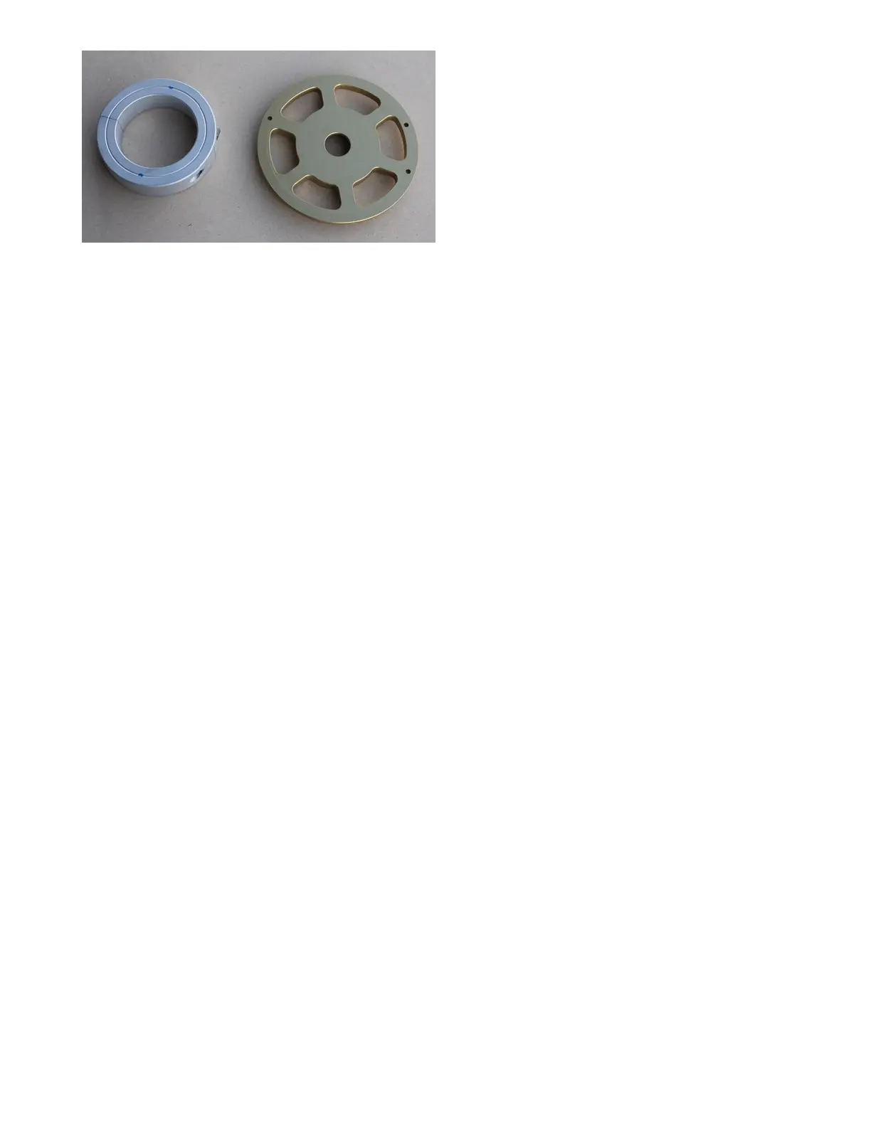
Jabiru and Rotax magnet discs
Set magnet air gap from the sensor to .050 - .080 inches by shimming the sensor or moving the collar
as the case may be.
Indexing of the magnet discs is not important on fuel-only systems. The ECU just needs a frequency.
4 cylinder engines will use 2 magnets 180 degrees apart, 6 cylinder engines have 3 magnets 120
degrees apart. These are called the trigger magnets.
If your engine has fuel and spark control, your magnet disc will have an extra magnet mounted,
inverted polarity from the rest. This is the synch magnet and identifies #1 cylinder to the ECU for
spark control purposes. You’ll also have a twin element Hall sensor instead of the single element one.
If you have spark control, you need to index the magnet disc so that, with the crank at TDC#1, the #1
trigger magnet (one of the equally spaced ones with the synch magnet closest to it) is 80 degrees
past the black squares on the Hall sensor, in the direction of crank rotation. See the diagrams in the F
Supplemental Manual.
Lycoming engines usually have fuel and spark control so magnet indexing is critical. The Hall
sensor is non-adjustable and bolts to a dedicated CNC’d mount on the right front side of the
crankcase, using the front-most case through bolts. Undo the nuts and be sure the bolts go through
the case with the heads on the left side and threads protruding on the right side. On 540 engines, the
upper fastener is a stud instead of a bolt as on the 4 cylinder engines. Be sure to have one standard
washer against the case on the right side in both cases. Screw the long hex nuts provided on in place
of the standard Lycoming nuts. Torque to 300 inch lbs. or as recommended for your model of engine.
Single ECU systems use a twin element sensor (red color) with a single cable. Twin ECU systems
use a quad element Hall sensor with 2 cables. Install the AN-6 bolts provided with one standard
washer under the head, through the gold bracket, into the hex nuts and tighten finger tight for now.
Extra thick and thin washers provided are to establish prop air gap from the magnets to sensor face
and from the edge of the sensor to the flywheel ID. See photos in the Ignition Supplement for more
detail. Be sure the Hall sensor bolts don’t hit the case bolts. If they do, place another washer under
the head of the Hall sensor bolts. Torque AN6 bolts to 215 in/lb. The 10-32 Allen bolts in the mount to
sensors are torque to 25 in/ lb. with blue Locktite on the threads, 30 in/lb. dry.
The magnets on Lycoming installations are mounted into the flywheel using the drilling/
tapping kit provided for your engine type. You must have the 8 7/16 ID flywheel. See the
separate detailed instructions included for your engine type.
Fuel Pump Cover
We supply a fuel pump plate to cover the hole where the old mechanical fuel pump was mounted.
Seal this with RTV before bolting in place. If you have the engine apart, you can leave the fuel pump
drive rod out (Lycoming), as it’s not required with the electric EFI fuel pumps.
 Loading...