Do you have a question about the SDS EM-5-D and is the answer not in the manual?
Products do not conform to standards; user assumes all responsibility for use and consequences.
Microprocessor-based, digital, programmable EFI system for port type injectors.
ECU uses sensor inputs to determine injector timing and duration based on engine parameters.
Importance of using properly sized and matched injectors for optimal performance and engine health.
Recommendations for adjustable and non-adjustable regulators and their proper setup.
Recommendations for using genuine Walbro pumps and proper installation procedures.
Guidelines for selecting and routing flexible fuel lines between airframe and engine.
Recommended Duplex selectors and importance of fuel filters, including annual checks.
Use of gascolators and procedures for welding injector bosses onto induction tubes.
Mounting EFI injectors directly into existing 1/8 NPT holes on Lycoming engine heads.
Adapter installation for AV engines, similar to parallel valve procedure.
Mounting ECU in passenger compartment, away from water and electrical noise sources.
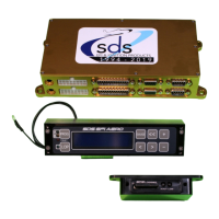
Identifying connectors for injector drive, main harness, and programmer on the EM-5 ECU.
Connecting programmer unit and 25-pin main harness to the ECU for system setup.
Wiring the Hall sensor for RPM signal and overview of ECU connections.
Detailed pinout for 25-pin main harness and 9-pin Hall sensor connectors.
Connecting the ECU injector outputs to the injector harness for proper fueling.
Using relay boxes to switch injector circuits between Primary and Backup ECUs.
Recommended breaker sizes for ECU, fuel pump, injectors, and other components.
Importance of backup power and recommendations for alternators or batteries.
Connecting programmer unit and mounting options for system access and diagnostics.
Proper mounting of the mixture knob for easy access and preventing accidental adjustments.
Installing various throttle body sizes for different Lycoming and Continental engines.
Installing TPS for throttle response and MAP sensor with correct orientation.
Installing CHT/Air temp sensors and routing cables away from spark plug wires.
D, F, and Lycoming F type sensors for fuel-only or fuel/spark control.
Specific mounts for Lycoming, Rotax, and Jabiru engines for correct sensor alignment.
Setting magnet air gap and indexing for spark control systems.
Understanding EM-5 resets, power interruption effects, and programmer disconnection.
How injector drivers are triggered and the function of the mixture knob for tuning.
Navigating parameters, viewing system status, and accessing settings via the LCD programmer.
Using gauge modes for real-time sensor data and understanding error codes (ERR).
Monitoring mixture knob, acceleration pump, duty cycle, and ignition timing (F models).
Recommended tuning sequence, startup procedure, and using AFR meter for fine-tuning.
Adjusting RPM Fuel and MAP values to determine base fuel injection and load-based fueling.
Setting up lean warning for protection against lean conditions, requires TPS and wideband O2.
Adjusting idle mixture, ACC pump for response, and engine temp for warmup enrichment.
Setting START and START CYCLES values for proper engine starting, especially in cold climates.
Recommendation to keep closed loop off and setting fuel cutoff limits for engine protection.
Locking values, using cylinder fuel trim, and configuring system setup mode.
Calibrating fuel pulse output for engine monitors and totalizers.
New programmer unit, LOP key, Fault LED, and A B Prog key functionality.
Copying values to backup ECU, switching between ECUs, and protection values.
Troubleshooting rich/lean mixtures and fuel delivery issues at high power.
Detailed pinout for DB25 and DB9 connectors, including wire colors.
Understanding check engine light causes and using gauge modes for sensor troubleshooting.
Diagnosing problems like no start, rough idle, misses, or unstable RPM readings.
Diagnosing cut-outs, cylinder misfires, lack of power, and programmer display errors.
Addressing engine fuel issues, RPM limits, and spark plug wire interference.
Using suppression type wires and resistor plugs to prevent electrical noise and interference.
Contacting support, warranty terms, and procedures for component repair or return.
Tach signal specs and critical warnings regarding VP-X circuit breaker sensitivity.
| Channels | 50 |
|---|---|
| Operating Temperature | -40°C to +85°C |
| Receiver Type | GPS |
| Update Rate | 1Hz |
| Position Accuracy | 2.5m CEP |
| Acquisition Time (Typical) | 29 seconds |
| Protocol | NMEA 0183 |