15
Dual ECU systems use relay boxes between the 16 pin Molex connectors and the connections to the
injector harness.
Relay box photo, 4 cylinder shown.
For 6 cylinder dual systems please see the 6 cylinder dual supplement manual for details.
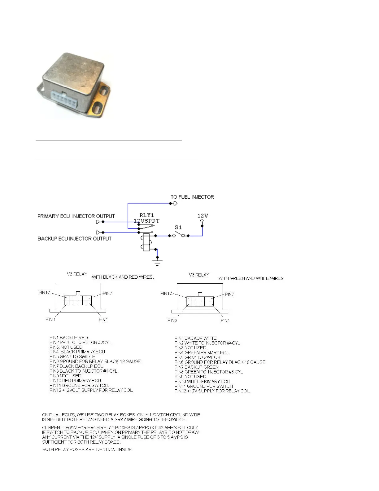
4cyl dual systems without individual cylinder trim: One injector relay box is used to switch fuel injector
circuits between Primary and Backup ECU.
4cyl dual systems with optional individual cylinder trim: Two injector relay boxes are used to switch
fuel injector circuits between Primary and Backup ECU. Each relay box switches 2 injector outputs. By
default relays are sending out the injector output from the Primary ECU. When the relay toggle switch
is turned on, the relay coils are energized and then the relays are sending out the output from the
Backup ecu. Below shows the schematic for one injector circuit for better understanding.