EasyManua.ls Logo

SDS EM-6 - User Manual

SDS EM-6
77 pages
Print Icon
To Next Page IconTo Next Page
Loading...
1
EM-6 Aviation Installation and Tuning Manual for Version 33 Software.
July 2/23
Disclaimer
These products do not conform to any recognized set of standards or certifications for aviation
applications.
This ECU is not waterproof and will not function as designed if moisture invades the enclosure or
power/ ground connections are interrupted.
Failure of this unit may result in a complete loss of engine power.
Use of these products on amateur built/ experimental aircraft is at the discretion of the buyer who
accepts full responsibility for any consequences resulting from its use. Since Racetech Inc.
cannot control the installation, programming, application environment or use of its products, we
accept no responsibility for damage, loss or personal injury resulting from the use of SDS
products. By using SDS products, the user understands and accepts this.
If any user does not agree to this disclaimer, they may return the system/ parts in new condition
for a full refund.
*********************************************************************************************************
Please read the entire manual before attempting any hookup or running of the system.
Due to the technical nature of this system and depending on the engine type, we may include
supplement manuals to cover different applications.
For tech help email Racetech/SDS at racetech1@telus.net or call 403-671-4015. When calling for help
please let us know which system you have. See below for descriptions of different systems.
System Description
SDS EM-6 is available in 2 different models for aviation applications:
EM-6-D controls fuel injectors only.
EM-6-F controls fuel and ignition timing using coil packs or multiple ignition coils.
EM-6 is a microprocessor based, digital, programmable EFI system intended to control port type injectors and
direct fire ignition coil packs. The EM-6 allows you to access all points in the engine operating map with the engine
running and alter them according to your own specific needs utilizing a panel mounted LCD programmer.
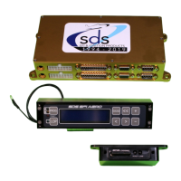
Dual EM-6 ECU with Design1 programmer and SDS card data logger shown
Question and Answer IconNeed help?

Do you have a question about the SDS EM-6 and is the answer not in the manual?

Overview

This document describes the SDS EM-6 Aviation System, an electronic fuel injection (EFI) and ignition control system designed for aircraft engines. It covers various components, their installation, wiring, operation, and troubleshooting.

Function Description

The SDS EM-6 system provides precise control over fuel injection and ignition timing for aviation engines. It uses an Electronic Control Unit (ECU) to manage these functions, aiming for optimal engine performance, fuel efficiency, and reliability. The system can operate in a single ECU or dual ECU configuration, with dual ECUs offering redundancy and the ability to control two sets of spark plugs independently. A programmer unit allows users to adjust various engine parameters and monitor sensor data.

Important Technical Specifications

ECU:

  • Dual ECU Configuration: Stacks two boards in a single box. The upper board is the Primary ("A" computer), and the lower is the Backup ("B" computer).
  • Sensor Suite (Dual 4-cyl): Primary ECU has full sensor suite (crank, MAP, temp, TPS, mixture knob). Backup ECU only has crank and MAP sensors.
  • Sensor Suite (Dual 6-cyl): Both ECUs have full sensor suites.
  • Mounting: Not waterproof; connectors should face down if mounted horizontally. Avoid mounting near DC motors or high-pulsing current/voltage wires (minimum 2-inch separation).
  • Hole Spacing: 3.37 x 8.08 inches for mounting.
  • Power: Switched 12V, fused with 2 Amp fuse (Red 20 gauge wire).
  • Ground: Connect two black ground wires to a grounding buss (not shared with other wires). Dual ECUs have 4 ground wires total.

Programmer:

  • Design1 EFI AERO Programmer: Rectangular (6.25 inches wide, 1.366 inches high) for panel mounting. Features ECU Pri/Bak select key and LOP key.
  • Older 3-1/8" Round Programmer: Fits standard 3 1/8 instrument cutout. Uses external switches for LOP activation and ECU selection.
  • Cables: Available in 3, 6, 10, and 15-foot lengths. Primary ECU connects to primary programmer port, backup to backup.

Fuel System:

  • Fuel Pressure Regulator: Adjustable Borla (AN-6 fittings) or non-adjustable OEM type. Recommended fuel pressure: 45 psi (engine not running). MAP reference hose port for intake manifold vacuum.
  • Fuel Pumps: Genuine Walbro/TI pumps recommended for reliability and safety. Can be single or dual, mounted in a module. Dual pumps require separate power feeds, breakers, and ground points. Fuse each pump with a 15 amp fuse/breaker.
  • Fuel Filters: Large single or two smaller (40 micron) before pump module, plus one small filter between pumps and fuel block. Rated to at least 100 psi.
  • Fuel Lines: Rigid aluminum/steel tubing or Teflon-lined, stainless steel braided flexible hoses. Flexible hoses must have a conductive inner liner. Never use rigid line between airframe and engine.
  • Injectors: Stainless steel body injectors for temperature resistance. Lycoming parallel valve engines use dedicated mounting system into 1/8 NPT holes. Lycoming angle valve engines use a different adapter.
  • Throttle Body: 60mm (O-320-O-540 vertical induction, carb/RSA-5 sump), 80mm (RSA-10 servo sump), or 45mm (O-200, <120hp engines). All have O-ring sealed bases and TPS provision.

Ignition System:

  • Hall Sensor: CNC'd mounts for Lycoming (4 and 6 cylinder) using 9.75" O.D. flywheel. Single or dual setup. Rotax 912 uses machined magnet disc and Hall sensor mount. Jabiru 2200/3300 uses split magnet collar.
  • Coilpacks: 4-cylinder coilpacks have integral drive transistors. 6-cylinder coilpacks use external drive modules. Mounted in any orientation.
  • Spark Plug Adapters: Brass adapters convert Lycoming 18mm plug threads to 14mm for automotive type plugs.
  • Spark Plugs/Wires: Always use resistor type spark plugs and radio suppression type spark plug wires (e.g., MSD 8.5mm Superconductor, NGK, OEM carbon string). Never use solid core wires.

Sensors:

  • MAP Sensor: Mount with vacuum port facing down to prevent moisture. Join to intake manifold/TB with 5/32 vacuum hose.
  • Temperature Sensors: 1/8 NPT, Bosch M 12 X 1.5mm, GM 3/8 NPT. Engine temp sensor typically in cylinder head (air-cooled) or coolant passage (water-cooled). Air temp sensor in intake air stream.

Usage Features

  • Programming: The programmer allows adjustment of fuel and ignition timing values, and displays engine sensor data. Parameters include RPM FUEL, MAP FUEL, Engine Temp, Start, Start Cycles, LOP (Lean of Peak) settings, Crank Retard, Magnet Position, and more.
  • Dual ECU Operation: In dual ECU systems, the Primary ECU typically runs injectors 1-3 and one set of spark plugs, while the Backup ECU runs injectors 4-6 and the other set of spark plugs. A selector switch allows switching injector control between ECUs for troubleshooting or redundancy.
  • Lean of Peak (LOP): Activates ignition advance and fuel leaning for cruise conditions. Requires Manifold Pressure <= LOP MAX MANIFOLD PRESSURE and Engine RPM >= 1500.
  • Mixture Knob: Allows quick leaning/richening of mixture without reprogramming. Recommended for permanent installation as an override control.
  • Data Logging: SDS Card Logger connects to the primary ECU via an audio cable, using a 32Gb card to continuously log ECU data.
  • Fuel Flow Output: Outputs a fuel pulse signal to engine monitors for fuel flow and totalizer amounts.
  • Test Functions: Injector test pulses (fuel pump off) and ignition test (spark plugs disconnected) for troubleshooting.
  • Safety Features: Fuel Cut/RPM and Fuel Cut/MAP limits protect the engine from over-revving or over-boosting.

Maintenance Features

  • Filter Checks: Check fuel filters annually, and at 10 hours initially for new build aircraft.
  • Troubleshooting: The manual provides extensive troubleshooting guides for various symptoms (engine not starting, cuts out at high power, rough idle, blank programmer display, etc.).
  • Check Engine Light: Indicates problems with MAP, engine/air temp, Hall sensor, or low battery voltage. Can be cleared via the programmer.
  • Electrical Connections: Critical for proper function. All wires, especially ground and power, should be properly soldered or crimped with heat shrink tubing for strain relief.
  • Sensor Alignment: Check Hall sensor alignment with magnets by rotating the crankshaft slowly.
  • Factory Default Values: Can be restored if programming issues arise.
  • Repairs/Returns: Racetech Inc. provides repair and warranty services. Prior authorization is required for returns.

This system is designed for experienced users and requires careful installation and programming to ensure safe and reliable operation in aviation applications.

SDS EM-6 Specifications

General IconGeneral
BrandSDS
ModelEM-6
CategoryGPS
LanguageEnglish

Related product manuals