16
The EM-5 can control a check engine light, L.E.D. or lamp to warn in the event of certain
sensor problems or failures.
This will not be supplied with systems in 2020 which have the newer programmer units with a
built in fault LED.
Using the SDS supplied lamp
Mount the lamp for best visibility for the pilot. Drill a 1/4” hole for
the lamp. Feed the wire through the hole from the front side of
the panel. You will need to connect the lamp’s red wire to a
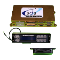
fused 12 volt circuit. The black wire from the check light needs to
be inserted in the drive harness white plug pin 11, see photo.
3
RD
position from the right on the top row. A 2 amp fuse for this
circuit is recommended.
Brown 20 gauge, pin 2 white Molex: This supplies fuel flow data
output (optionally enabled)
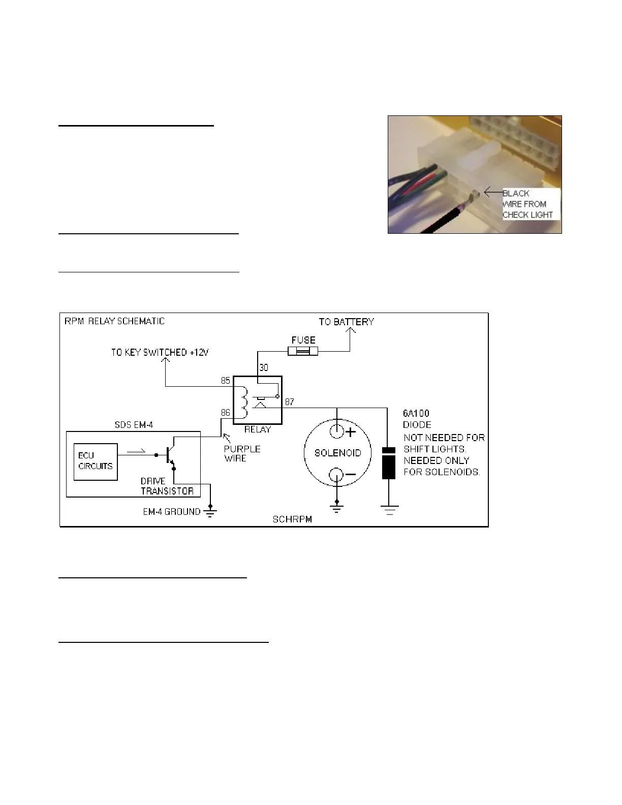
Purple20 gauge, pin 3 white Molex: Optional rpm switch, commonly used on VVT (Honda VTEC)
systems.
Ground switched. Hookup schematic below:
Orange 20 gauge, pin 1 White Molex: Optional fuel pump relay trigger wire. Ground switched. We
generally don’t recommend using this function on aviation systems. Each fuel pump should have a
separate switch, power wire, fuse/ breaker and ground wire (not grounded to the same
terminal).
Blue 20 gauge, pin 13 Main 25 pin D Sub: Ignition advance switch on F systems only. Feed 12 volts to
this wire via a panel mounted toggle switch to activate extra ignition advance over the programmed
values. Mainly used for LOP operation and as an octane selector when switching between 100LL and
Mogas. See the F manual for more information
For “F” systems (coil pack) there will be a white 2 or 3 conductor cable marked “CP”. This cable will
be connected to the coil pack’s input cable.
 Loading...