9
ECU Mounting and Wiring Considerations
The ECU should be mounted in the passenger compartment in an area where they cannot get wet. If
mounted horizontally, be sure the wiring harnesses have a drip loop to prevent water from running
down them, into the ECU. The ECU is not waterproof! If possible, mounting the ECU with the
connectors facing down gives the best protection against water ingress. Never mount the ECU on
top of the radio stack or within 3 inches of any DC motors or high pulsing current/ voltage
wires or devices. The ECU does not need any cooling or vibration isolation.
You should plan the ECU mounting to make wiring routing from it logically flow towards your firewall
grommet holes. For best possible resistance to electrical noise, we prefer to have all ECU and other
low level voltage/ current wires (thermocouples etc.) routed on one side of the firewall and all other
airframe wires which carry higher voltages and current (alternator, starter, DC motors etc.) routed on
the opposite side of the firewall and engine compartment. Never tie wrap high voltage/current
wires such as the starter, spark plug wires, alternator, strobes, radio transmitter, transponder,
DC motors etc. to any of the ECU wiring. A minimum 3 inch separation is preferred.
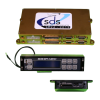
EM-5 ECU connectors
Injector drive Main harness Hall Programmer
The dual board ECU enclosure stacks 2 boards in a single box. The upper board, closest to the lid, is
the Primary or “A” computer. The lower, closest to the mounting flange is the Backup or “B”computer.
The optional PC data logging function can only be connected to the “A” computer. On 4 cylinder
models using the dual board ecu, there is no TPS, air temperature sensor, CHT sensor or mixture
knob connected to the backup computer since these are non-critical to running the engine. 6 Cyl dual
board models use two air temp and two CHT sensors, but share the TPS signal.
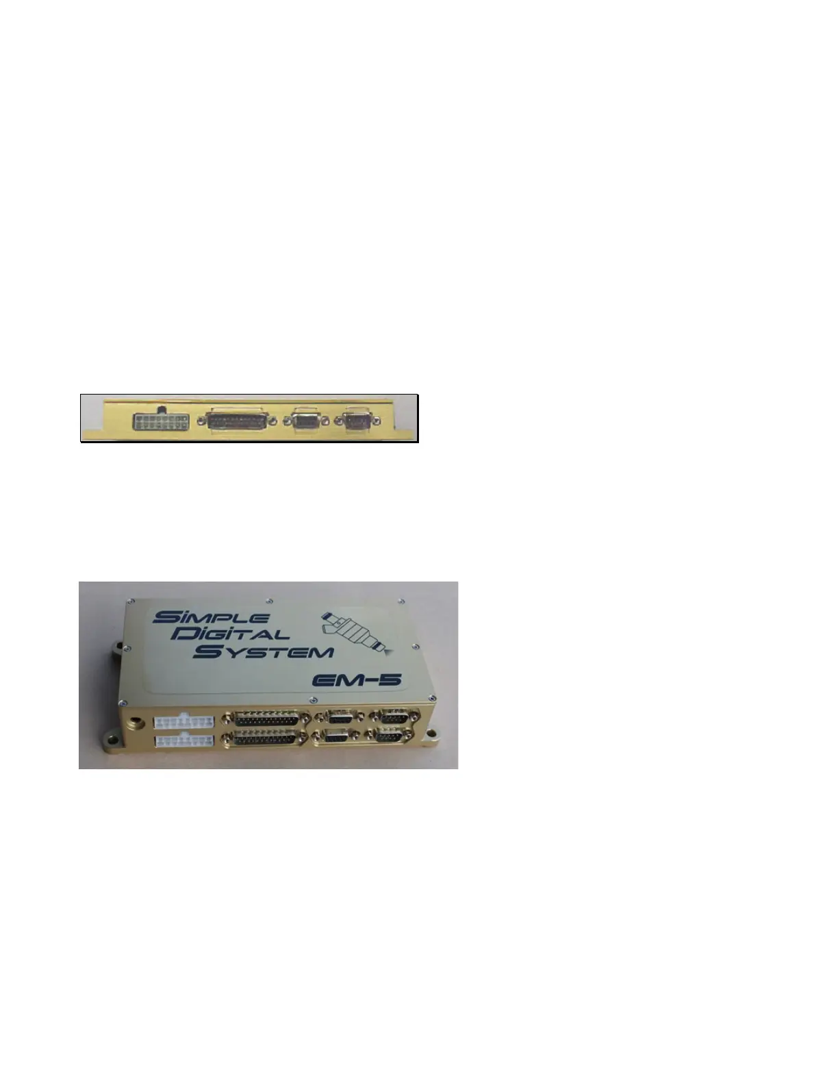
Dual board ECU
Dual board ECUs generally are used on engines with 2 spark plugs per cylinder. One ECU board
drives the upper plugs and the other board drives the lower plugs at all times. A relay switch box is
used to switch injector outputs between the 2 boards. The upper board is the Primary ECU, lower is
the Backup.
The dual board ECU also uses a special programmer with dual serial ports in the back, one
connecting to each ECU with a toggle switch to select each ECU. Upper ECU board plugs into lower
programmer connector.
 Loading...