13
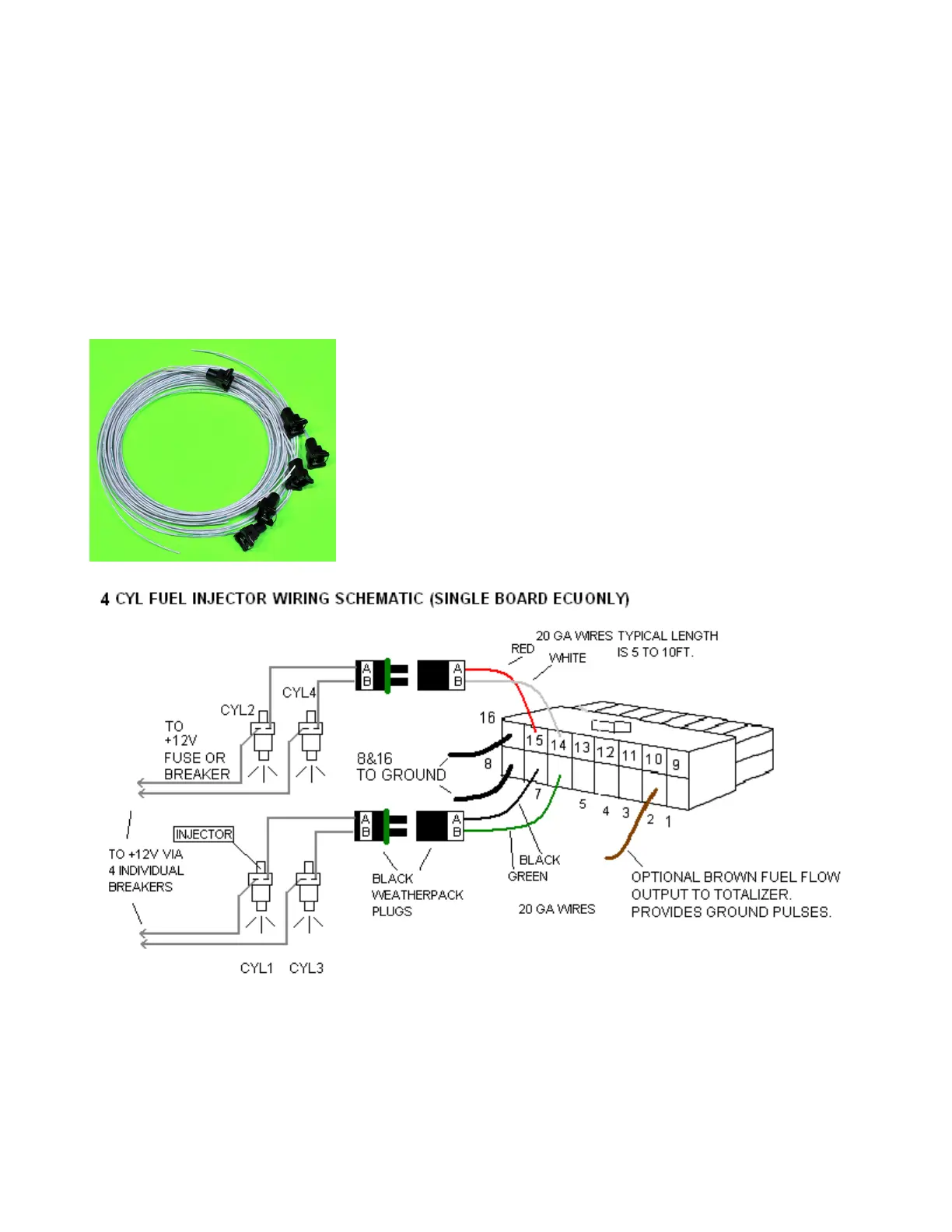
Single board ECU Injector Drive Harness and wiring from 16 Pin White Molex to Injectors
This connects the ECU injector outputs to the injector harness and also contains the injector ground
wires and the option control wires. The two short black wires from pin 8 &16 should go to separate
airframe grounds and have no other wires grounded to the same point. On Dual ECU systems
the Drive harness will connect via injector relay box(es). Details below.
Injector Harness
This plugs into the drive harness on one end and the injectors on the other end. One side of each
injector will go to the appropriate drive harness wire from the 16 pin white ECU, or in the case of dual
ECUs, from the injector relay boxes. The other injector wire will go to switched 12V. Fuse each of
these power wires with a 5 amp fuse/ breaker. This gives some redundancy for a breaker or shorted
injector failure. Be sure to connect the proper wire colors from the drive harness plug to the correct
injector number when using the fuel trim option. See the layout schematic at the end of the manuals.
For 6 cylinder dual ecu’s see the supplement manual.
 Loading...