Do you have a question about the Sea Breeze PTAC49CH3ZX and is the answer not in the manual?
General safety guidelines for installation and repair work, emphasizing codes and careful step following.
Warnings and precautions regarding electrical work, emphasizing licensed technicians and high voltages.
Precautions related to physical installation, unit weight, tubing, and outdoor unit placement.
Warnings about handling refrigerants, including decomposition hazards and proper usage.
Safety measures during maintenance, including power disconnection and avoiding moving parts.
Cautionary advice on installation locations and environmental factors like gas leaks and water.
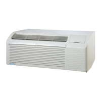
Detailed technical specifications for 208/230 VAC PTAC units, including capacities, dimensions, and electrical data.
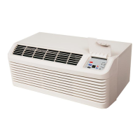
Detailed technical specifications for 265/277 VAC PTAC units, including capacities, dimensions, and electrical data.
Instructions for installing the unit chassis, including recommendations for sleeves and seals.
Steps and warnings for preparing wall sleeves for unit installation, including GE and Carrier sleeves.
Step-by-step guide for inserting and securing the PTAC unit into a wall sleeve, including panel removal and reinstallation.
Defines the temperature parameters used for unit operation: indoor setting temperature (Tpeset) and room temperature (Tamb).
Explains the basic operation of the compressor, including start-up delays and stop conditions across different modes.
Details the operating conditions and process for the cooling mode, including fan speed and temperature thresholds.
Describes the fan-only mode, including fan speed selection and ambient temperature display.
Explains the heating mode operation for both electric heater and heat pump units, including temperature controls.
Describes the unit's OFF mode, power indicator, and how buttons affect the display.
Details the conditions for activating and deactivating low temperature resistant protection.
Explains error codes and unit behavior when temperature sensors have open or short circuits.
Overview of the unit's buttons (ON/OFF, MODE, FAN SPEED, UP, DOWN) and display indicators (LEDs, digital display).
Lists error codes displayed via the STATUS LED for various malfunctions and protection states.
Describes special functions like Energy Management Input (EM) and configuration options via dip switches.
Explains how to enter and navigate configuration mode for display settings, temperature offsets, and display switching.
Explains timer usage, power-off memory, and restoring factory settings.
Explains the entry and quit conditions for frost protection mode in heat pump units.
Details the conditions for activating and deactivating high temperature protection for the evaporator.
Describes the entry and quit conditions for anti-freezing protection of the evaporator.
Explains the conditions for activating and deactivating high temperature protection for the outdoor condenser.
Identifies potential causes and solutions for the unit failing to start up, such as power supply or fuse issues.
Addresses issues where the unit operates but does not provide cooling or heating, covering fan, refrigerant, and load problems.
Troubleshoots fan motor start-up, speed problems, and controller malfunctions.
Diagnoses why the compressor won't start despite a normal output signal, checking capacitors, wiring, and motor condition.
Provides steps for diagnosing and resolving issues related to refrigerant and system blockages.
Troubleshoots electric heater operation, high outdoor temperatures, load suitability, and room air tightness.
Guides on checking and correcting unstable supply voltage and incorrect wiring connections.
Addresses overheating protection, frequent compressor cycling, and remote control/display issues.
Offers solutions for abnormal vibration and noise, including checking base stability, installation, and foreign objects.
Provides a table correlating ambient temperatures with resistance values for the ambient temperature sensor.
Lists resistance values for outdoor and indoor tube temperature sensors across various temperatures.
Step-by-step instructions for removing the front panel assembly, including releasing clasps and potentially removing filters.
Instructions for disassembling the outer case, involving pulling the unit and case apart and removing screws.
Steps to remove middle connection board, support sub-assembly, and top cover plate.
Instructions for disassembling the electric box, including removing the leading-out box, control cover plate, and wiring terminals.
Details on removing the middle isolation sheet, involving screws and angling.
Instructions for unsoldering and removing the 4-way valve assembly, noting refrigerant discharge.
Steps to unsolder and remove suction and discharge pipes, emphasizing refrigerant discharge.
Instructions for removing the compressor by unscrewing nuts and removing the drainage valve by unscrewing screws.
| Voltage | 230/208 V |
|---|---|
| Height | 16 inches |
| Phase | 1 |
| Refrigerant | R-410A |
| Air Flow | 350 CFM |
| Weight | 120 lbs |
| Type | PTAC (Packaged Terminal Air Conditioner) |
| Width | 42 in |