EasyManua.ls Logo

Sea Ray 290 Select EX User Manual

Sea Ray 290 Select EX
68 pages
To Next Page IconTo Next Page
Page #1 background imageLoading...
Page #1 background image
290 Select EX
Owners Manual Part Number: MRP 1803657
This owners manual is arranged into two parts. Following is a description of each.
General Information
This section contains general information you need to know to safely operate
and maintain your boat.
Specific Information
This section contains information that is specific to your boat such as dimensions, general
arrangement, specific safety information, special features and the electrical system.
If any of these sections are missing from this book contact your dealer.
Your dealer can find out when it will be available and order it for you.
Sea Ray
Owners
Manual
Question and Answer IconNeed help?

Do you have a question about the Sea Ray 290 Select EX and is the answer not in the manual?

Sea Ray 290 Select EX Specifications

General IconGeneral
Holding Tank Capacity28 gal (106 L)
Sleeping Capacity4
Draft22"
Fuel Capacity130 gal
Engine OptionsMerCruiser 6.2L MPI

Summary

Supplemental General Information

Life Saving Equipment (PFD)

Information on storage, operation, and maintenance of personal flotation devices.

General Arrangements and Dimensions

Boat Specifications

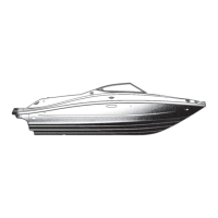
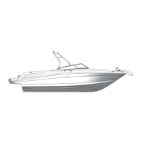
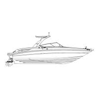
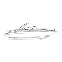
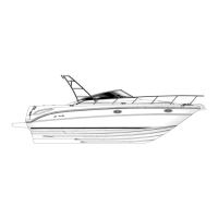
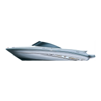
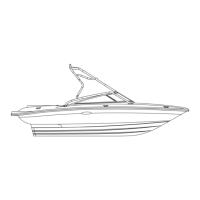
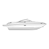
Detailed dimensions, weight, and capacities of the 290 SLX model.

Dash Layout

Dash Gauge Layout

The main instrument cluster showing engine and boat operational data.

Engine Gauge Cluster (Twin Engine)

Engine Compartment Layout (Single Engine)

Gasoline Single Engine Components

Diagram showing component locations within the engine compartment for a single engine.

Engine Compartment Layout (Twin Engine)

Gasoline Twin Engine Components

Diagram showing component locations within the engine compartment for twin engines.

Fire Extinguishing System

Automatic Fire Suppression System

Location, indicator panel, and extinguisher requirements for the automatic system.

Engine Systems

Engine Cooling and Oil Change

Information on engine cooling and the oil change system, including plug locations.

Electrical Information

Battery Switch Functionality

Description of the dual battery switch and its role in power distribution.

Electrical Component Locations

Battery Switch and DC Breaker Panel Locations

Identification of where the battery switches and main DC breaker panel are situated.

Electronic Switch Pads and EIMs

Locations of electronic switch pads and interface modules (EIMs) for boat controls.

Ground Fault Interrupter (GFI) Outlet

GFI Outlet Location and Loads

Details on the GFI outlet's placement and the associated electrical loads.

Electronic Switch Pads and EIMs

Locations of Electronic Switch Pads and EIMs

Diagrams showing the locations of electronic switch pads and EIMs.

Main DC Distribution Panel

Main DC Breaker Panel Diagram

Diagram and list of DC breakers located in the aft port cockpit compartment.

Main Distribution Panel

Main AC Distribution Panel Diagram

Diagram of the main distribution panel for AC power distribution within the cabin.

DC Wiring Schematic (1 of 4)

Instrument Panel DC Wiring Schematic

DC wiring schematic for the instrument panel and related components.

DC Wiring Schematic (2 of 4)

Port Switch Pad DC Wiring Schematic

Detailed DC wiring schematic for the port switch pad and its connections.

Starboard Switch Pad DC Wiring Schematic

Detailed DC wiring schematic for the starboard switch pad and its connections.

Aft EIM DC Wiring Schematic

Detailed DC wiring schematic for the aft electronic interface module.

DC Wiring Schematic (4 of 4)

Main DC Breaker Panel DC Wiring Schematic

DC wiring schematic for the main DC breaker panel.

DC Wiring Schematic (Twin Engine Option) (1 of 4)

Twin Engine Control Station Gauge Panel DC Wiring Schematic

DC wiring schematic for the twin engine control station gauge panel.

DC Wiring Schematic (Twin Engine Option) (2 of 4)

Twin Engine Port Switch Pad DC Wiring Schematic

Detailed DC wiring for the port switch pad on twin engine models.

Twin Engine Starboard Switch Pad DC Wiring Schematic

Detailed DC wiring for the starboard switch pad on twin engine models.

Twin Engine Aft EIM DC Wiring Schematic

Detailed DC wiring for the aft electronic interface module on twin engine models.

DC Wiring Schematic (Twin Engine Option) (4 of 4)

DC Wiring Schematic (Twin Volvo Diesel) (1 of 4)

Twin Volvo Diesel Control Station Gauge Panel DC Wiring Schematic

DC wiring schematic for the twin Volvo diesel control station gauge panel.

DC Wiring Schematic (Twin Volvo Diesel) (2 of 4)

Twin Volvo Diesel Port Switch Pad DC Wiring Schematic

Detailed DC wiring for the port switch pad on twin Volvo diesel models.

Twin Volvo Diesel Starboard Switch Pad DC Wiring Schematic

Detailed DC wiring for the starboard switch pad on twin Volvo diesel models.

Twin Volvo Diesel Aft EIM DC Wiring Schematic

Detailed DC wiring for the aft electronic interface module on twin Volvo diesel models.

DC Wiring Schematic (Twin Volvo Diesel) (4 of 4)

Main DC Breaker Panel Wiring Diagram

Main DC Breaker Panel Wiring Connections

Wiring diagram for the main DC breaker panel, showing connections and layout.

DC Wiring Schematic (Twin Diesel) (Option)

Twin Diesel Control Station Gauge Panel DC Wiring Schematic

DC wiring schematic for the control station gauge panel on twin diesel models.

Twin Diesel Port Switch Pad DC Wiring Schematic

Detailed DC wiring for the port switch pad on twin diesel models.

Twin Diesel Starboard Switch Pad DC Wiring Schematic

Detailed DC wiring for the starboard switch pad on twin diesel models.

SmartCraft Systems Diagram

Related product manuals