Do you have a question about the Sea Ray 38 Sundancer and is the answer not in the manual?
Identifies safety labels located within the cabin area of the boat.
Identifies safety labels located at the helm station of the boat.
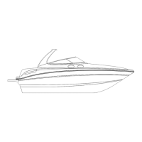
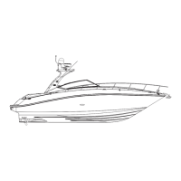
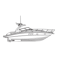
Details key physical dimensions, including length, beam, draft, and height.
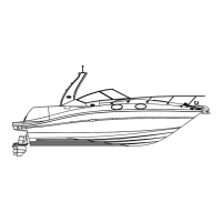
Illustrates and names through-hull fittings on the starboard side.
Illustrates and names through-hull fittings on the port side.
Shows through-hull fittings located in the bilge area.
Identifies through-hull fittings located on the transom.
Overview of the helm layout, showing major controls and instruments.
Detailed view of the gauges and displays on the instrument panel.
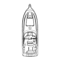
Top-down view of the main deck, showing various features and equipment.
Top-down view of the arch structure, showing antenna and radar placements.
Interior cabin layout, detailing galley, berths, and seating areas.
Diagram showing the placement of cleats and bow/stern eyes.
Details the location and operation of navigation and anchor lights.
Diagram illustrating the bilge system components for gas models.
Explains the function of the TV antenna/cable selector panel.
Instructions for connecting a television to dockside cable.
Details the salon television and its operation.
Describes the entertainment system in the master stateroom.
Information on connecting and using the boat's telephone system.
Diagrams detailing the boat's direct current electrical wiring systems.
Specific DC wiring diagrams for the boat's cabin systems.
Wiring diagrams for the boat's engine harnesses.
Diagrams for system monitor and gauge connections.
Wiring diagrams for windlass and stereo systems.
Diagrams for antenna, bow thruster, and interconnect systems.
Wiring diagrams for the boat's generator systems.
Diagrams of the boat's alternating current electrical wiring systems.
Wiring diagrams for the Smartcraft engine monitoring system.
| Sleeping Capacity | 6 |
|---|---|
| Draft | 3' 4" |
| Length Overall | 38' 6" (11.73 m) |
| Beam | 12' (3.66 m) |
| Engine Options | Twin MerCruiser 8.2L MAG HO (430 HP each) or Twin MerCruiser 6.2L MPI (350 HP each) |