Do you have a question about the Sea Ray AMBERJACK 250 and is the answer not in the manual?
Information on PFD storage, operation, and maintenance.
Guidance for troubleshooting performance, engine, and electrical systems.
Contact information for Sea Ray customer service and parts.
Instructions on using cleats, bow/stern eyes for handling the boat.
Diagram and details of the bow eye for mooring and lifting.
Diagram and details of stern eyes for tie-downs and service lifting.
Diagram showing the location of cleats on the boat.
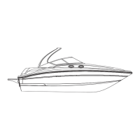
Technical specifications including length, beam, draft, weight, and capacities.
Dimensions related to height, such as waterline to windshield.
Layout of the seating arrangement within the boat.
Floor plan illustrating the main deck layout and features.
Floor plan showing the mid-deck layout, including galley and head.
Safety warning about securing the anchor independently.
Personal injury hazard warning for specific areas while underway.
Slipping hazard warning for wet decks.
Danger warning about engine shutdown near swimmers.
Location of the speaker on the forward panel.
Diagram showing electronics located behind the dash panel.
Location of the light and other components near the battery switch.
Information and operation of the boat's head system.
Cautionary note regarding items not to be placed in the head.
Diagram showing the standard waste water line routing.
Diagram illustrating waste water routing for the international option.
Diagram identifying key components in the bilge area.
Location and function of the bilge pump and its float switch.
Location of the fire extinguisher in the bilge.
Diagram showing the fresh water line routing.
Diagram showing the routing of various drain lines on the boat.
Diagram illustrating the routing of battery cables.
Information and location of the battery on/off switch.
Diagram showing the fuel line routing for the standard gasoline system.
Diagram illustrating fuel line routing for the optional diesel system.
Diagram showing the installation of the bilge blower.
Diagram showing the installation of the bilge pump and float switch.
Diagram showing the routing of power steering lines.
Diagrams of automatic fire extinguisher systems for gasoline and diesel engines.
Location and function of the fire extinguisher discharge port.
Safety warnings for using the fire extinguisher discharge port.
Information on the engine cooling system.
Diagram and details of the anchor arrangement.
Identifies through-hull fittings on the starboard side of the boat.
Identifies through-hull fittings on the port side of the boat.
Diagram showing hull cutouts for various fittings.
Illustration of the gauge panel with various gauges.
Overview of the switch panel and its controls.
Layout of the dash for a single engine configuration.
General information and safety warnings related to boat canvas usage.
Details of standard and optional sport boat canvas packages.
Locations of switches and lights in galley, cabin, and head areas.
Location of components under throttle and near fire extinguisher.
Wiring diagrams for the instrument panel.
Diagram showing wire routing near the helm access door.
Diagrams illustrating cabin harness installation and overall routing.
Wiring connections for the instrument panel.
Wiring diagram for the ignition switch panel.
Wiring for the electronic interface module.
Wiring connections related to the engine.
Wiring diagram for the battery switch.
Wiring details for the control station.
Wiring diagram for the ignition switch panel with Smartcraft.
Wiring for the electronic interface module with Smartcraft.
Wiring connections for the engine with Smartcraft.
Wiring diagram for the battery switch with Smartcraft.
Wiring details for the control station with Smartcraft.
Wiring for the engine monitor panel.
Wiring for the electronic interface module.
Wiring diagram for the instrument panel with Volvo.
Wiring for the ignition switch panel with Volvo.
Wiring for the electronic interface module with Volvo.
Wiring related to the Volvo D3 engine.
Wiring for the ignition switch panel.
Interconnection wiring for the instrument panel.
Interconnection wiring for the electronic interface module.
Interconnection wiring for the secondary switch panel.
Interconnection wiring for engine controls.
French, Italian, Spanish, and EC directive authorities.
Canadian authority for ship safety standards.
Japanese craft inspection and classification society authorities.
British Standards Institute and Det Norske Veritas.
| Category | Boat |
|---|---|
| Model | AMBERJACK 250 |
| Manufacturer | Sea Ray |
| Beam | 8' 6" |
| Draft | 2' 0" (0.61 m) |
| Holding Tank Capacity | 20 gal (76 L) |
| Deadrise at Transom | 20° |