INSTALLATION
MANUAL
Section 3: COOLING INSTALLATION
3.2 CONNECTING SEAWATER TO HEAT EXCHANGER
Refer to Figure 2 for typical seawater plumbing arrangement.
1. Connect seawater pump to Seakeeper dedicated through-hull fitting. A strainer and seacoc
k
valve should generally be installed between the seawater inlet and the pump.
2. Connect seawater from installer-supplied seawater pump to lower 1/2” (13 mm) hose barb on
heat exchanger.
a. Use the same practices as other below waterline seawater plumbing.
3. Connect seawater discharge (upper hose barb) to overboard drain. Use the same practices as
other below waterline seawater plumbing.
4. During commissioning, seawater flow should be checked to be within the flow requirements
while the vessel is at rest, at speed, and when backing down.
a. If no other method of confirming flow is available, discharge line may be temporarily
diverted to a bucket. Flowrate is calculated based on the time required to fill a known
volume in GPM / LPM.
b. Flowrates in excess of 4 GPM (15.2 LPM) could affect heat exchanger life.
5. After sea trial / commissioning, inspect all raw water plumbing for any signs of leakage.
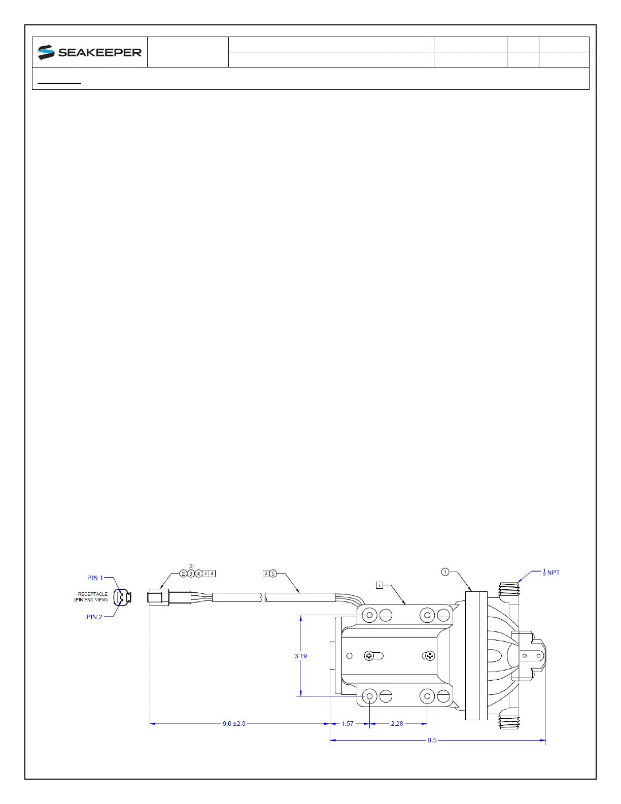
3.3 SEAKEEPER 1 DC SEAWATER PUMP P/N 30331 (OPTIONAL)
1. Seakeeper offers a self-priming DC Seawater pump as an optional addition, P/N 30331 – DC
Sea
water Pump, Seakeeper 1 Assembly, shown in the following Figure
.
2. T
he Seakeeper Seawater Pump is a 24 VDC pump operated at 12 VDC for the Seakeeper 1 an
d
m
aintains a seawater flow of approx. 2.5 GPM (9.5 LPM) at 12V DC
.
3. The
pump assembly is pre-wired for connection to Seakeeper 1 CABLE 5 and includes
a
seawater strainer and various fittings. The pump specifications are as follows:
i. Volts
: 2
4 VDC (operate at 12v for Seakeeper 1)
ii. Rated Flow: 2.5 GPM (9.5 LPM), at 12 VDC
iii. Overcurrent Protection Rating: 15 A
iv. Ignition Protection: ISO 8846 or equiv.
Figure 3: Seakeeper 1 DC Seawater Pump
 Loading...


