INSTALLATION
MANUAL
Product: Document #: Rev: Page:
SEAKEEPER 6 90402 1 5 of 5
Section 3: COOLING INSTALLATION
5) The cooling system is self-purging. If small amounts of air are in the system, they will
most likely be dislodged during the first sea trial. Re-check level after sea trial and add fluid if
required.
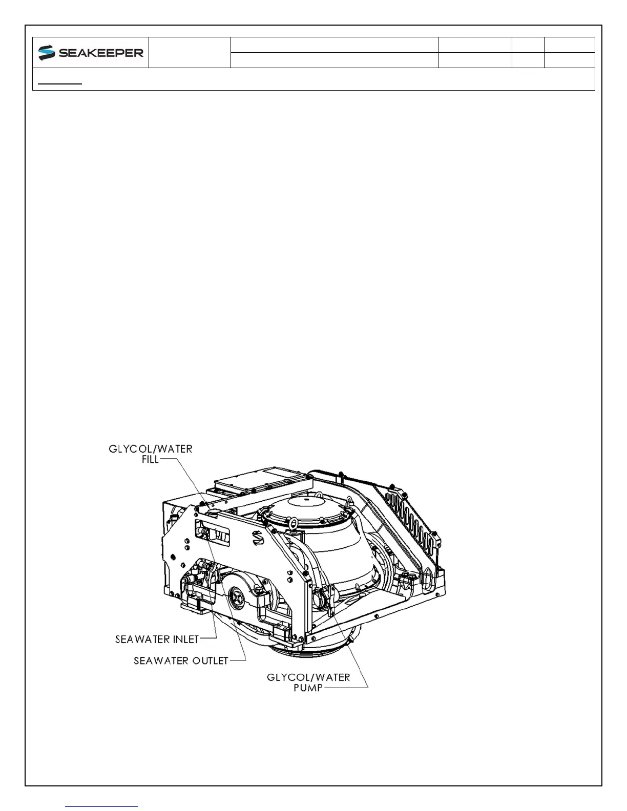
3.3 Connecting Seawater to Heat Exchanger
1) Connect seawater from installer supplied pump to lower 3/4” (19 mm) hose barb on heat
exchanger. Use the same practices as other below waterline seawater plumbing.
Required flow rate is 4 GPM (16 LPM) minimum and 8 GPM (30.3 LPM) maximum.
2) Connect seawater discharge (upper hose barb) to overboard drain. Use the same
practices as other below waterline seawater plumbing.
3) In addition to initial operation at dock, new installations should be checked for minimum
4 GPM (16 LPM) flow while vessel is at speed and when backing down. If no other
method of confirming flow is available, discharge line may be temporarily diverted to a
bucket. Flow is calculated from time to fill a known volume.
4) Inspect raw water plumbing after sea trial for any signs of leakage.
5) Heat exchanger contains removable end-caps to provide access for cleaning the tube
bundle.
FIGURE 4 – SEAKEEPER 6 SEAWATER CONNECTIONS
 Loading...