INSTALLATION
MANUAL
Product: Document #: Rev: Page:
SEAKEEPER 6 90402 1 2 of 6
Section 1: MECHANICAL INSTALLATION
1.1 Precautions
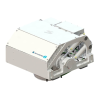
Seakeeper must only be lifted from the supplied lifting eyes (See Section 1.4).
Seakeeper flywheel is supported by precision bearings. Make certain while unpacking
and lifting Seakeeper assembly to NOT drop or impart mechanical shock as damage to
bearings could result.
While handling / installing Seakeeper assembly, protect exposed hydraulic brake cylinder
rods (See Figure 1) from scratches or damage as this could lead to premature seal failure
and oil leaks.
While handling / installing Seakeeper assembly, do not allow electrical fittings that exit
bottom of Seakeeper enclosure to come in contact with any surface or object as this could
damage the fittings and potentially affect the vacuum integrity of the enclosure.
Exercise care to protect the painted finish as damage to finish could lead to early
appearance degradation of installed Seakeeper.
1.2 Selection of Installation Location
Selection of mounting location of Seakeeper should consider the following desirable
features:
The Seakeeper must be installed aft of amidships to minimize high
acceleration loadings due to hull/wave impacts during operation at
high speed or in large waves.
Overhead access or sufficient clearance for removal / re-installation of Seakeeper
for overhaul in future years.
Seakeeper should be installed in a dry space to minimize effects of corrosion.
Clearance for replacement of gimbal angle sensor on gimbal shaft (see Figure 2).
Clearance for filling / purging brake hydraulic oil (see Figure 2).
Clearance for filling water/glycol cooling circuit (see Figure 2).
Clearance for replacement of brake hydraulic cylinders (see Figure 2).
Clearance for routine and regular maintenance including Anode replacement on the Heat
Exchanger (see Figure 2).
 Loading...