5. ASSEMBLY
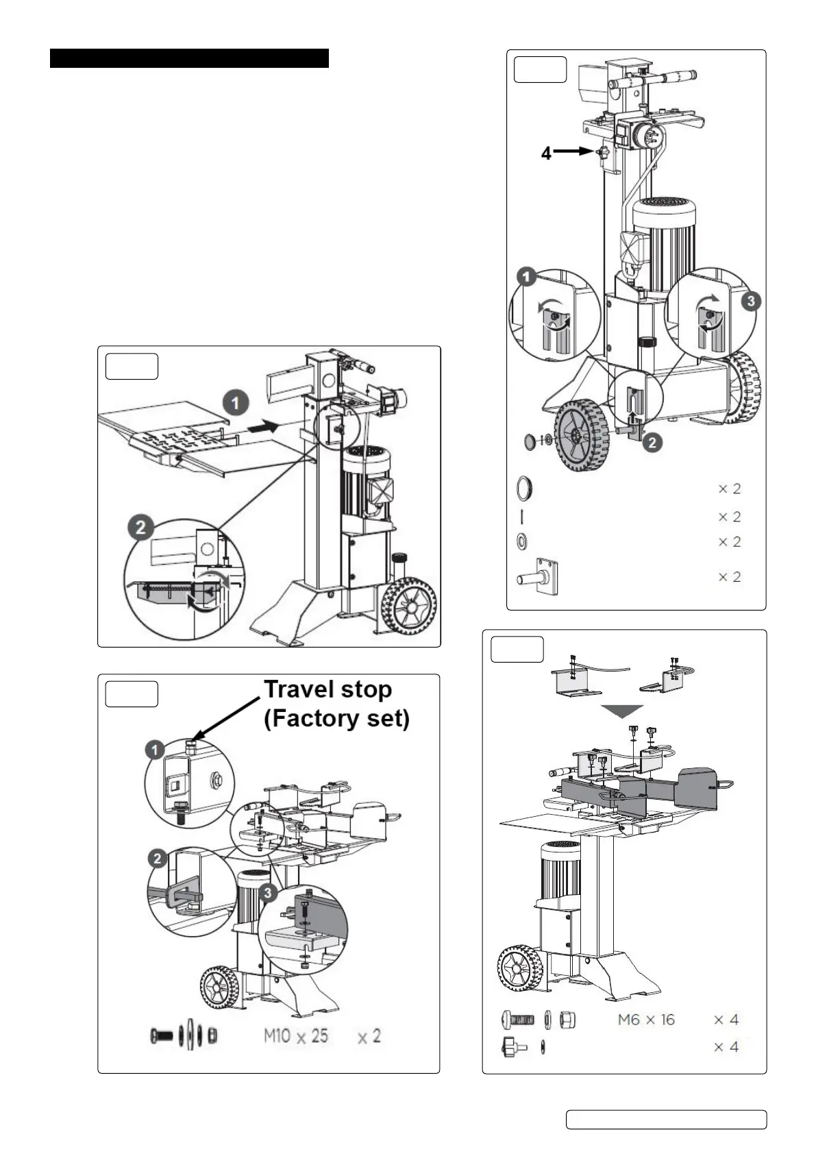
5.1. WHEELS(g.2)
5.1.1. Loosen wheel hub mounting brackets (g.2.1).
5.1.2. Slide wheel shaft assemblies into brackets and tighten in situ (g.2.2, g.2.3).
5.1.3. Slide wheels onto shafts followed by washers and pin in place using split pin.
5.1.4. Fit wheel hub caps into wheel centre.
5.2. SUPPORTTABLE(g.2,g.3)
5.2.1. Loosen support table locking knob on splitter frame (g.2.4).
5.2.2. Fully unfold Support table (g.1.6) and insert hook features into the mounting
brackets on the splitter frame (g.3.1). Re-tighten the locking knob to rmly hold
support table in place (g.3.2).
5.3. CONTROLLEVERANDGUARDASSY(g.1.2,g.4)
5.3.1. Insert M10 x 25 bolts and washers into holes at end of guard tubes (g.4.1).
5.3.2. Locate control lever section into slot at end of control arm (g.4.2).
5.3.3. Place large at washer (supplied) between lever support bracket and control
lever section and secure rmly in place using washer and nut from
underside (g.4.3).
5.3.4. Factory set travel stops are positioned at the end of the control arm (g.4.1).
Arm travel can be adjusted if required by screwing the stops either in or out.
Original Language Version
© Jack Sealey Limited
fig.
2
fig.
3
fig.
4
fig.
5
LS550V Issue 2 (2) 02/10/19