This document outlines the instructions for Sealey Power Welders Inverters, specifically models MW140.V2, MW140PLUS, MW150, and MW170. It covers safety, electrical specifications, operational procedures, maintenance, and electromagnetic compatibility.
Function Description
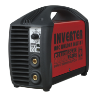
These inverters are designed for manual arc welding with covered electrodes (MMA) and TIG welding. They are lightweight, powerful, and versatile, featuring "Scratch-Start" method for arc ignition. The MW140.V2 and MW140PLUS models are equipped with Arc-Force circuitry for improved arc stability, anti-sticking, and hot-start features, along with thermal overload protection. The MW150 and MW170 models offer additional functionality with a selection switch for different welding dynamics: TIG for maximum arc current stability, HARD for maximum welding dynamics (hot start and arc force suitable for basic and aluminium electrodes), and SOFT for welding with rutile and inox electrodes. The MW140PLUS model includes a supply filter to minimize damage from unstable power supplies, making it suitable for use with generators.
Important Technical Specifications
The rating plate on the rear of the inverter provides key technical data:
- Standard Conformity: EN 60974-1, indicating compliance with safety and construction standards for arc welding equipment.
- Type: Inverter-transformer-rectifier.
- Welding Procedure: Manual arc welding with covered electrode.
- Environmental Suitability: Marked with 'S', indicating suitability for use in environments with heightened risk of electric shock (e.g., close to large metallic objects).
- Power Supply: Single-phase AC, 1~50/60Hz.
- Internal Protection: IP23 (Ingress Protection rating).
- Output:
- Uo: Maximum open-circuit voltage.
- I2, U2: Current and corresponding voltage.
- X: Welding ratio based on a 10-minute cycle (e.g., 30% indicates 3 minutes welding and 7 minutes rest; 100% indicates continuous welding).
- A/V-A/V: Welding current adjustment range and corresponding voltages.
- Power Supply Ratings:
- U1: Rated supply voltage and frequency.
- Imax: Maximum current.
- I1eff: Maximum effective current.
- Fuse Rating: 13 AMP for MW140.V2 & MW140PLUS only. Products requiring more than 13 amps are supplied without a plug, requiring professional installation.
- Welding Current Regulation: Adjustable via a potentiometer, with a scale graduated in Amps. Recommended welding currents vary by electrode diameter:
- 1.6mm: 25-50 Amp
- 2.0mm: 40-80 Amp
- 2.5mm: 60-110 Amp
- 3.2mm: 80-160 Amp
- 4.0mm: 120-200 Amp
Usage Features
- Electrical Safety: Requires checking all electrical products for safety before use, including power cables, plugs, sockets, and connectors. Installation of an RCCB (Residual Current Circuit Breaker) or RCD (Residual Current Device) is recommended. All portable electrical appliances used in business premises must be tested annually with a Portable Appliance Tester (PAT). The appliance voltage must match the power supply, and the correct fuse must be fitted. Damaged cables, plugs, or connectors must be immediately repaired or replaced by a qualified electrician. For UK 3-pin plugs, specific wiring instructions are provided (Green/Yellow to Earth 'E', Brown to Live 'L', Blue to Neutral 'N'). Extension reels should be fully unwound and have a cable core section of at least 1.5mm², preferably 2.5mm², and ideally fitted with an RCD.
- Generator Use: Caution is advised when using a diesel generator. The generator must be stable in frequency, voltage, and waveform, with an output higher than the inverter's power (kVA) and must be self-regulating. Using a generator without a regulator can be dangerous and voids the inverter warranty.
- Work Area: The inverter should be located in a suitable work area with adequate ventilation to dissipate welding fumes. The area should be clean, tidy, and free from conductive dusts, corrosive vapours, or humidity. Adequate lighting is essential.
- Cable Connections: Cable connectors must be fully turned into quick plugs to ensure good electrical contact, preventing overheating and loss of efficiency.
- Protective Gear: Operators must wear a welding head shield to protect eyes and face from ultraviolet rays, and safety welding gauntlets. Ill-fitting clothing, ties, watches, rings, and loose jewellery should be removed, and long hair contained.
- Workpiece Security: The workpiece must be correctly secured before operating the inverter.
- Arc Welding (MMA): Strike the electrode tip on the workpiece like striking a match, avoiding hitting it forcefully to prevent damage. Once the arc ignites, maintain a distance from the workpiece equal to the electrode's diameter. Keep this distance constant and maintain an angle of 20° to 30° as you advance. To finish a weld bead, bring the electrode backward to fill the crater, then quickly lift it to extinguish the arc.
- TIG Welding: Uses an arc between a tungsten electrode and the work to fuse the joint. Filler metal may be required. The process is protected by an inert gas shield (usually pure argon, but helium or argon/hydrogen mixtures can be used). Strike the electrode tip on the workpiece like a match, avoiding forceful hits. Point the electrode at the weld direction, about 2.5mm from the surface. Gas flow is controlled by a knob on the torch handle. Filler metal (cut lengths of wire over 1.5mm diameter) is added to the leading edge of the weld pool.
- Controls:
- Potentiometer: Regulates welding current.
- Yellow LED (MW140.V2 & MW140PLUS): Normally off. Illuminates when there is no welding current due to thermal protection, mains over/under voltage protection (over 260V or under 190V), or short circuit (lasting over 1.5 seconds, e.g., electrode sticking). Re-start is automatic.
- Green LED (MW140.V2 & MW140PLUS): Mains power indicator, machine ready.
- Function Selection Switch (MW150 & MW170): Selects TIG, HARD, or SOFT welding dynamics.
Maintenance Features
- Disconnection: Always unplug the inverter from the mains power supply and wait for the short-circuit light (fig 4. B) to go out (10-15 seconds for capacitor discharge) before connecting/disconnecting cables or performing maintenance. Direct contact with the inverter circuit is dangerous.
- Cleaning: Periodically remove the cover and lightly dust the inside of the machine with low-pressure air. Ensure the cover is correctly replaced and secured. Keep the outside of the machine clean by wiping with a soft, dry cloth.
- General Maintenance: The equipment should be routinely maintained according to instructions. All access and service covers must be closed and properly fastened. The equipment should not be modified except for changes and adjustments covered in the instructions. Spark gaps of arc striking and stabilising devices should be adjusted and maintained.
- Cables: Welding/cutting cables should be kept as short as possible and positioned close together, running at or close to floor level.
- Troubleshooting: If problems occur, check the welding current, power lamp status, yellow LED status, fan operation, correct voltage, cable condition, and circuit connections (especially the work clamp).
Electromagnetic Compatibility (EMC)
The equipment conforms to European standards for EMC in arc welding. However, it may still cause interference to radio and television reception if used within 30m of an antenna. Users are responsible for resolving interference, potentially by earthing the circuit, constructing an electromagnetic screen, or using input filters. An assessment of the surrounding area for potential electromechanical problems is required before installation, considering other supply cables, control cables, signalling/telephone cables, radio/TV transmitters, computer/control equipment, safety-critical equipment, health of people (pacemakers, hearing aids), calibration/measurement equipment, and immunity of other equipment. Mains supply should be connected according to instructions, and shielding of the supply cable may be necessary. All metallic components in the welding/cutting installation and adjacent to it should be considered for equipotential bonding, but operators must be insulated from such components to prevent electric shock. Earthing the workpiece may reduce emissions, but care must be taken to avoid increasing injury risk or damage to other equipment. Selective screening and shielding of other cables and equipment may alleviate interference problems.