EasyManua.ls Logo

Sealey PPVT User Manual

Sealey PPVT
4 pages
To Next Page IconTo Next Page
Page #1 background imageLoading...
Page #1 background image
INSTRUCTIONS FOR
AUTOMOTIVE TEST PROBE
MODEL NO: PPVT
Thank you for purchasing a Sealey product. Manufactured to a high standard, this product will, if used according to these instructions,
and properly maintained, give you years of trouble free performance.
IMPORTANT: PLEASE READ THESE INSTRUCTIONS CAREFULLY. NOTE THE SAFE OPERATIONAL REQUIREMENTS, WARNINGS & CAUTIONS. USE
THE PRODUCT CORRECTLY AND WITH CARE FOR THE PURPOSE FOR WHICH IT IS INTENDED. FAILURE TO DO SO MAY CAUSE DAMAGE AND/OR
PERSONAL INJURY AND WILL INVALIDATE THE WARRANTY. KEEP THESE INSTRUCTIONS SAFE FOR FUTURE USE.
1. SAFETY
9 If you are in any doubt about electrical safety consult a qualified electrician.
9 Only for use with 2V - 24V DC systems.
8 DO NOT apply voltage or current to the probe that exceeds the specified maximum of 24V DC.
8 DO NOT use with industrial 110V systems.
8 DO NOT use on any circuit directly or indirectly connected to AC lines or any other AC power source.
8 DO NOT use with any component or circuits of the vehicle’s ignition system.
9 Before using this device, check the vehicle’s electrical wiring and disconnect any part or system sensitive to voltage and current pulses
such as air bags, electronic control modules, etc.
9 Always check your instructions and procedures indicated in the vehicle service manual before attempting to disconnect any part or sub-
system of the electrical circuit.
9 When not in use, store the meter carefully in a safe, dry, childproof location. Avoid extremes of temperature.
8 DO NOT use the unit around explosive gases, vapour or dust. When the power switch is operated (forwards or backwards), battery
current is conducted to the tip of the probe which may cause sparks when contacting ground or certain other circuits.
8 DO NOT use leads if damaged or if the wire is bared in any way.
8 DO NOT use the equipment when you are tired or under the influence of alcohol, drugs or intoxicating medicines.
8 DO NOT use this tester for any purpose other than that for which it has been designed.
2. INTRODUCTION
Time saving tool ideal for the automotive electrician and mechanic. Connects to the vehicle’s own battery and reaches all corners of the
vehicle with 5mtr cable. Checks for shorts circuits and bad earths quickly and easily. Tests continuity and polarity using flying lead and
also indicates voltage (2V to 24V) of system on test using an LED array. Power-up components prior to installation and check in situ
function of components and accessories allowing fast problem diagnosis. Features integral work light with touch sensitive control.
1. Red Battery Clip
2. Black Battery Clip
3. Probe
4. Work Light
5. Test Indicator
6. Voltage Indicators
7. Power Switch
8. Selection Switch
9. Work Light Touch Switch
10. Auxiliary Earth Lead
3. OPERATION
3.1. BASICCONNECTIONS(g.2).
3.1.1. Unroll the unit’s cable. Attach the red battery clip to the positive (+) terminal on the vehicle’s battery and the black clip to the negative
(-) terminal on the vehicle’s battery. The test probe will commence a self test for several seconds, with the buzzer sounding, green test
indicator, red test indicator and the built in work light all illuminating in sequence.
3.2. QUICK SELF TEST.
3.2.1. With the battery clips still attached press and hold down the power switch (7) in the single bar ‘POSITIVE’ position. The test indicator
(5) should illuminate RED.
3.2.2. Press and hold down the power switch (7) in the double bar ‘NEGATIVE’ position. The test indicator should illuminate GREEN.
3.2.3. The unit is now ready to use. If the test indicator did not illuminate, the cause may be that the battery clip connections are poor or the
unit is damaged.
3.3. WORK LIGHT OPERATION.
3.3.1. With the battery clips attached, contact the auxiliary earth lead (10) to the work light touch switch (9) for about 1 second, then remove.
Toturno󰀨worklight,contactauxiliaryearthlead(10)withworklighttouchswitch(9)forabout1secondagain.
Refer to
instruction
manual
fig.
1
Wear protective
gloves
Wear eye
protection
Corrosive
substance
PPVT Issue 2 (H, F) 23/02/18
Original Language Version
© Jack Sealey Limited
Warning:
Explosive gas
Question and Answer IconNeed help?

Do you have a question about the Sealey PPVT and is the answer not in the manual?

Sealey PPVT Specifications

General IconGeneral
BrandSealey
ModelPPVT
CategoryTest Equipment
LanguageEnglish

Summary

Safety Instructions

General Safety Guidelines

Key safety precautions and warnings for operating the automotive test probe, emphasizing electrical safety.

Electrical System Precautions

Rules for safe use with 2-24V DC systems, avoiding AC or ignition systems, and checking vehicle manuals.

Introduction to Automotive Test Probe

Product Overview and Components

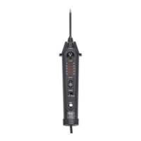
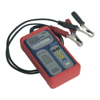
Description of the test probe's utility, features like 5m cable and work light, and a list of its parts.

Basic Connections and Self-Test

Connecting Battery Clips

Steps to attach the red and black battery clips to the vehicle's battery terminals for initial setup.

Performing Quick Self-Test

Procedure to verify the test probe's functionality by testing positive and negative connections.

Work Light Operation

Instructions on how to activate and deactivate the integrated work light using the auxiliary earth lead.

Measuring DC Voltage

Voltage Measurement Procedure

Steps for setting the selection switch to 'VOLTAGE' and connecting the probe to measure circuit voltage.

Polarity Testing

Polarity Test Steps

How to test circuit polarity by connecting the probe to positive or negative points, indicated by LED color.

Continuity Testing

Continuity Test Procedure

Method for testing wire and component continuity by connecting the probe and auxiliary earth lead.

Activating Components

Activating Components (Positive)

Procedure to power components with positive voltage, testing their function using the probe.

Activating Components (Negative)

Procedure to power components with negative voltage, testing their function using the probe.

Jumper Lead Feature

Using as a Jumper Lead

How to use the unit as a long jumper lead by disconnecting the red battery clip.

Checking for Bad Earth Contacts

Earth Contact Testing

Method to identify good or bad earth connections by probing and observing the test indicator.

Locating Short Circuits

Short Circuit Finding Process

Steps to find short circuits, starting with blown fuses and tracing wires using the test probe.

Testing Trailer Lamps

Trailer Lighting System Check

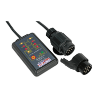
Procedure to test trailer lamp function and orientation by probing the connection socket.

Spare Part Information

Available Spare Parts

Details of available spare parts, specifically listing the probe with its part number.

Environmental Protection and Warranty

Product Disposal and Recycling

Guidelines for environmentally responsible disposal and recycling of the product and its components.

Warranty and Liability

Information on the product's 12-month warranty, non-liability for misuse, and potential product alterations.

Related product manuals