V-belts etc.
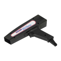
5.5. OperationalModeSwitchprocedure(g.2)
5.5.1. Set display to Mode 1 for distributor type ignitions
5.5.2. Set display to Mode 4 for 2 stroke and direct ignition systems.
5.6. TESTING PROCEDURE
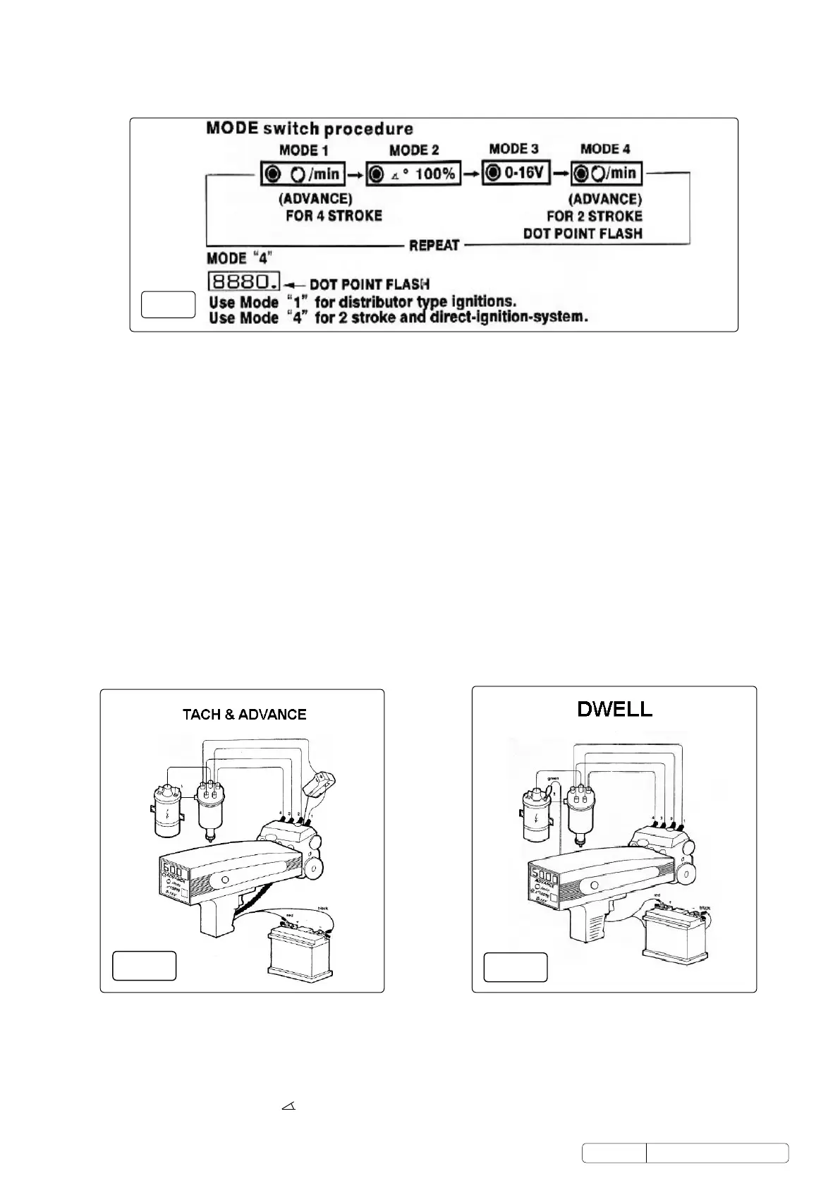
5.6.1. The timing light works directly with the car battery. Connect the red clip to the positive (+) terminal and the black end to the negative
terminal(-)(seeg.3).
5.6.2. Thelightpulseisusuallytriggeredbytheignitionpulseoftherstcylinder.Thismaydierinsomevehicles,thereforeconsultyour
owners manual.
5.6.3. Attach the inductive clamp to the clean ignition cable so that the arrow shown on the clip points in the direction of the spark plug.
5.6.4. Start the engine, which should be at operating temperature and bring it up to adjustment speed (rpm) recommended by
the manufacturer. Press the switch on the handle of the timing light. The Advance indicator will be lighted. Point the timing light at the
timing marks. The two marks should normally be opposite each other. If this is not so, proceed as in point 5.6.5 below.
5.6.5. Loosen the clamping of the fastening screws on the distributor until the distributor can be turned by hand. DO NOT loosen it too far
otherwise the distributor will turn by itself.
5.6.6. Turn the distributor clockwise or anticlockwise until the rotating mark is in the position recommended by the vehicle manufacturer.
5.6.7. Retighten the screws you have loosened so that the distributor setting is maintained.
5.6.8. Recheck the timing.
5.7. VEHICLES WITH POSITIVE EARTH
5.7.1. If the vehicle has a positive earth electrical system it is possible that the Xenon lamp does not light up. In this case reverse the
inductive clamp so that the arrow points in the direction of the distribution.
5.8. CHECKING THE CENTRIFUGAL ADVANCE AND VACUUM ADVANCE
5.8.1. Follow the steps 5.6.1 To 5.6.4 of the general procedures except increase the engine speed to 2000rpm.
5.8.2. Trigger the timing light and rotate the knob clockwise slowly and stop until the timing mark moves to “TDC” or “0” position.
5.8.3. ReadotheadvanceanglefromtheLEDdisplay.
5.8.4. Comparethereadingwiththemanufacturer’sspecications.
5.9. DWELL ANGLE MEASUREMENT
5.9.1. Dwell angle measurement is indispensable for exact distributor adjustment. For only when the dwell angle is correctly adjusted can a
powerfulmagneticeldbuildupwithinthecoil,thusprovidingahighenergyignitionsparkatallenginespeeds.
5.9.2. PressthetactswitchtolighttheDwellindicator(g.4).
5.9.3. Connect the green clip to terminal 1 of the ignition coil (1, D, RUP, -).
5.9.4. Start the engine and let it run at idle speed.
5.9.5. Readothedwellanglein%fromtheLEDdisplayandcompareitwiththemanufacturer’srecommendations.Pleaserefertothe
conversion table of Dwell Angle %
Original Language Version
© Jack Sealey Limited
fig.
2
TL93.V2 Issue 2 (H, F) 16/02/18
fig.4
fig.3
 Loading...