EasyManua.ls Logo

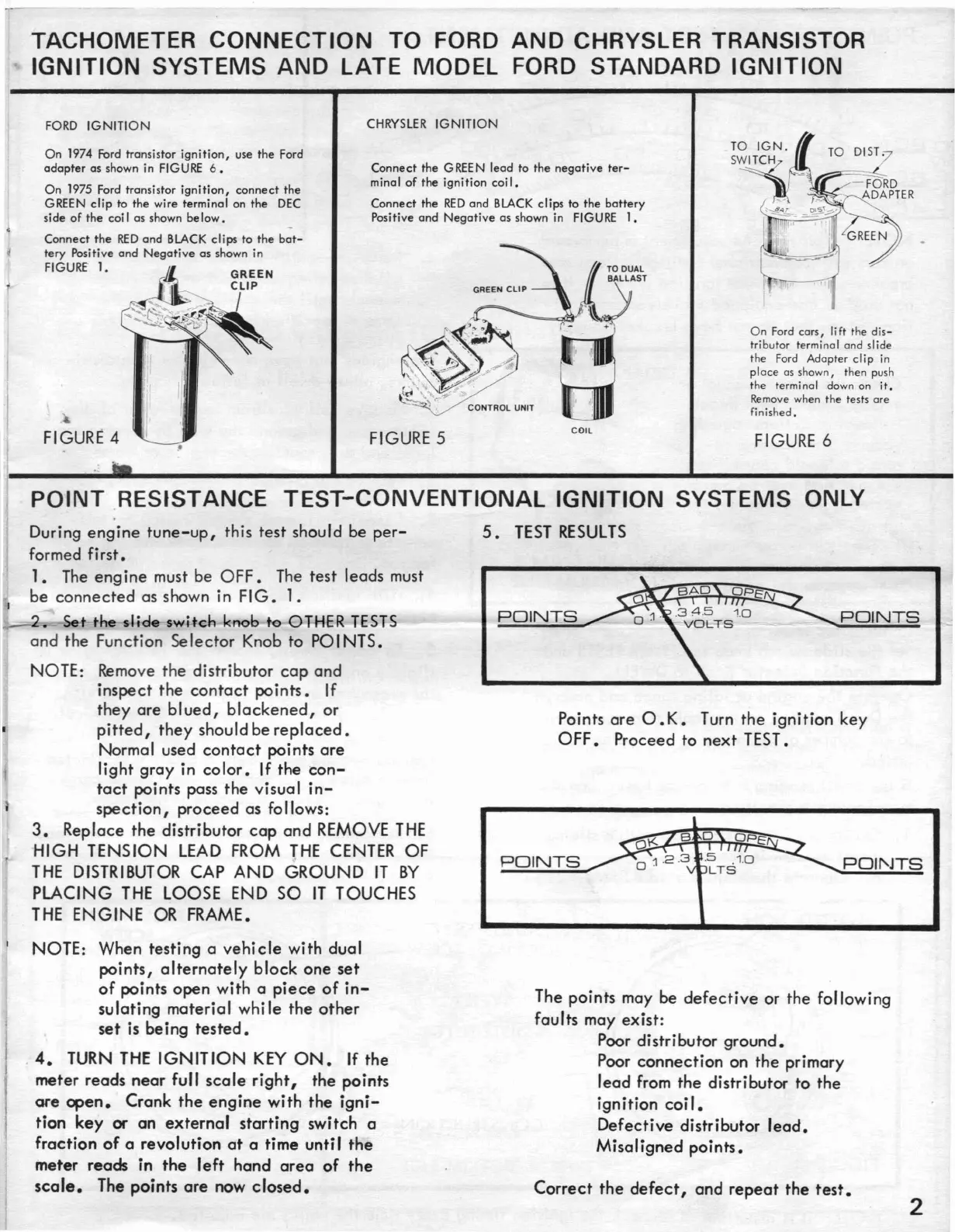
Sears 161.2161 - Engine Analyzer Connections (Ford & Chrysler Systems); Ford & Chrysler Ignition System Connections; Point Resistance Test; Conventional Ignition Systems Only

Sears 161.2161
8 pages
Print Icon
To Next Page IconTo Next Page
To Previous Page IconTo Previous Page
Loading...
TACHOMETER
CONNECTION
TO FORD
AND
CHRYSLER TRANSISTOR
IGNITION
SYSTEMS
AND
LATE
MODEL
FORD STANDARD
IGNITION
On
Ford cars,
Ii
ft
the
dis-
tributor terminal and slide
the Ford Adopter
clip
in
place
as shown, then push
the terminal down on
it.
Remove
when the tests are
finished.
Connect
the
GREEN
lead
to
the
negative
ter-
minal
of
the
ignition
coi
I.
Connect
the
RED
and
BLACK
clips
to
the
battery
Positive
and
Negative
as
shown in FIGURE
1.
CHRYSLER
IGNITION
GREEN
CLIP
I
FORD
IGNITION
Connect
the
RED
and
BLACK
clips
to
the
bat-
tery
Positive
and
Negative
as
shown in
FIGURE"
1.
On
1974 Ford transistor
ignition,
use
the
Ford
adapter
as
shown in FIGURE
6.
On
1975 Ford transistor
ignition,
connect
the
GREEN
clip
to the wire
terminal
on
the
DEC
side
of
the
coi I
as
shown
be
low.
FIGURE 4
..
FIGURE 5
COIL
FIGURE 6
POINT
.RESISTANCE
TEST-CONVENTIONAL
IGNITION
SYSTEMS
ONLY
Points
are
O.
K.
Turn
the
ignition
key
OFF.
Proceed
to
next
TEST.
5.
TEST
RESULTS
POII'JTS
POINTS
POINTS
POINTS
During
engine
tune-up,
this
test
should be
per-
formed
first.
1. The
engine
must be
OFF.
The
test
leads must
be
connected
as shown in
FIG.
1.
•
Se-t
the
slide
swi.-tch
knob to-OTHER
TESl-S
and
the
Function
Selector
Knob
to
POI NTS.
NOTE: Remove
the
distributor
cap
and
inspect
the
contact
points.
If
they
are
blued,
blackened,
or
pitted,
they
should
be
replaced.
Normal used
contact
points
are
light
gray
in
color.
If
the
con-
tact
points
pass
the
visual
in-
spection,
proceed
as follows:
3.
Replace
the
distributor
cap
and
REMOVE
THE
HIGH
TENSION
LEAD
FROM
THE
CENTER
OF
THE
DISTRIBUTOR CAP
AND
GROUND
IT
BY
PLACING
THE
LOOSE END
SO
IT
TOUCHES
THE
ENGINE
OR
FRAME.
NOTE: When
testing
a
vehicle
with
dual
points,
alternately
block
one
set
of
points
open
with
a
piece
of
in-
sulating
material
while
the
other
set
is
being
tested.
4.
TURN
THE
IGNITION
KEY
ON.
If
the
meter
reads
near
full
scale
right,
the
points
are
open.
Crank
the
engine
with
the
igni-
tion
key
or
an
external
starting
switch
a
fraction
of
a
revolution
at
a
time
until
the
meter
reads
in
the
left
hand
area
of
the
scale.
The
points
are
now
closed.
The
points
may be
defective
or
the
following
faults
may
exist:
Poor distributor
ground.
Poor
connection
on
the
primary
lead
from
the
distributor
to
the
ignition
coil.
Defective
distributor
lead.
Misaligned
points.
Correct
the
defect,
and
repeat
the
test.
2