EasyManua.ls Logo

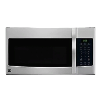
Sears 721.63263301 User Manual

Sears 721.63263301
43 pages
To Next Page IconTo Next Page
Page #1 background imageLoading...
Page #1 background image
DIVISION 20
BASIC FIELD MANUAL
FOR
MICROWAVE OVEN
MODEL 721.62252200 / 721.62252201
721.62259200 / 721.62259201
721.62253200 / 721.62253201
721.63263300 / 721.63263301
May, 2005
MODEL 721.62252
721.62259
721.62253
721.63263
Question and Answer IconNeed help?

Do you have a question about the Sears 721.63263301 and is the answer not in the manual?

Sears 721.63263301 Specifications

General IconGeneral
BrandSears
Model721.63263301
CategoryMicrowave Oven
LanguageEnglish

Summary

Safety Precautions for Servicing

Microwave Energy Exposure Avoidance

Essential safety measures for technicians to avoid microwave energy exposure during servicing.

Foreword

Manual Introduction and Safety Warning

Overview of the manual and a general warning about microwave energy.

Installation and Operation Guidelines

Installation Precautions

Proper power source, placement, and surface requirements for installation.

General Usage Precautions

Guidelines for operating the oven safely, including load and material use.

Trial Operation Guide

Steps to verify oven functionality after installation.

Specifications

Technical Data and Component List

Detailed specifications including power, dimensions, and parts.

Overall Circuit Diagram

Electrical Schematic Overview

Provides the schematic of the oven's electrical system for service.

Control Panel Operation

Touch Key Matrix and Functions

Explains the touch key input matrix and control panel button functions.

Easy Use Reference

Quick Guide to Oven Functions

Step-by-step instructions for common oven features like timer and defrost.

Microwave Leakage Measurement

Leakage Measurement Procedure

Detailed steps and equipment for measuring microwave energy leakage.

Disassembly Instructions

Removing Outer Case and Circuit Board

Instructions for safely disassembling the oven and removing the control circuit board.

Door Assembly Removal

Removing the Door Gross Assembly

Instructions for removing the entire door assembly and associated covers.

Component Removal: Magnetron and Suction Guide

Magnetron and Suction Guide Removal Steps

Steps for removing the magnetron and suction guide assembly.

Component Removal: Fans, Transformers, Sensors

Fan Motor, HV Transformer, and Sensor Removal

Instructions for removing fan motor, high voltage transformer, and sensor.

Component Removal: Capacitors, Motors, Interlocks

HV Capacitor, Turntable Motor, and Interlock System

Steps for removing HV capacitor, turntable motor, and interlock system components.

Interlock System Testing

Continuity Test for Interlock Switches

Procedures to test the continuity of primary, secondary, and monitor interlock switches.

Component Testing Procedures

Resistance and Continuity Tests

Guidance on testing major electrical components like transformers and capacitors.

Checkout Procedures: Fuse and Relay Issues

Troubleshooting Fuse Blowing

Identifies causes and remedies for fuse blowing issues.

Checkout Procedures: Circuit Board Issues

Relay and Circuit Board Troubleshooting

Diagnoses issues related to relays and the main circuit board.

Troubleshooting Common Issues

Oven Not Working or Low Power

Addresses issues like the oven not working or having low output power.

Troubleshooting Control Circuit Issues

Visual Indicators of Defective Control Circuit

Symptoms indicating a faulty control circuit board or keypad.

Troubleshooting Operation Issues

Oven Unresponsive or No Input Accepted

Diagnoses problems where the oven is unresponsive or shows no display.

Troubleshooting Cooking Issues

Cooking Start and Heat Production Problems

Addresses issues like failure to start cooking or low heat output.

Troubleshooting Oscillation and Power Issues

No Microwave Oscillation or Incorrect Power Output

Diagnoses problems related to microwave generation and power level accuracy.

Exploded Views Overview

Component Identification Diagrams

Visual breakdown of the microwave oven parts for identification.

Door Parts Exploded View

Detailed Door Assembly Components

Diagram showing individual parts of the microwave door.

Control Panel Parts Exploded View

Detailed Control Panel Components

Diagram showing individual parts of the control panel.

Oven Cavity Parts Exploded View

Detailed Oven Cavity Components

Diagram showing parts within the main oven cavity.

Latch Board Parts Exploded View

Detailed Latch Board Components

Diagram showing parts of the latch board mechanism.

Interior Parts Exploded View (I)

Detailed Interior Components (Part 1)

Diagram of internal components like fan motor and transformer.

Base Plate Parts Exploded View

Detailed Base Plate Components

Diagram showing components mounted on the base plate.

Sensor Parts Exploded View

Detailed Sensor Components

Diagram of the sensor and its mounting parts.

Related product manuals