Do you have a question about the Sears Craftsman 113.20680 and is the answer not in the manual?
Learn tool application, limitations, and specific hazards for safe operation.
Ensure proper grounding with 3-conductor cord and plug to prevent electric shock.
Maintain guards in proper working order, adjusted and aligned for safety.
Always remove tools before starting the machine to prevent accidental operation.
Maintain a clean, well-lit work area free of clutter to prevent accidents.
Operate tools in dry, well-lit locations and avoid damp or wet conditions.
Ensure children are kept a safe distance from the work area during operation.
Secure tools to prevent unauthorized or unsafe use by children.
Use the tool at its designed rate for safer and better performance.
Utilize the correct tool for the job to ensure safety and efficiency.
Wear appropriate clothing and safety gear to avoid entanglement with moving parts.
Always wear safety goggles to protect eyes from flying debris during operation.
Use clamps or a vise to secure workpiece for safer, hands-free operation.
Maintain proper footing and balance at all times to avoid losing control.
Keep tools sharp, clean, and properly lubricated for safe performance.
Disconnect power before servicing or changing accessories for safety.
Ensure the switch is off before plugging in the tool to prevent unintended startup.
Use only manufacturer-recommended accessories to avoid hazards.
Avoid standing on the tool to prevent tipping or accidental contact with cutters.
Inspect for damaged parts before use and repair or replace as needed.
Feed work into the blade against the direction of rotation for proper cutting.
Turn off the tool and ensure it stops completely before leaving it unattended.
Securely bolt the machine to the floor if it tends to tip or move during operation.
Position the jointer-planer to avoid operators standing in the path of the workpiece.
Understand kickback causes and how to avoid them through proper technique and setup.
Essential safety measures including eye protection, avoiding awkward positions, and using guards.
Guidelines for connecting the tool to a properly grounded 110-120V outlet.
Verify correct motor rotation direction before operating the machine.
Lists all loose parts included with the jointer-planer for verification.
Step-by-step instructions for assembling the steel legs for the jointer-planer.
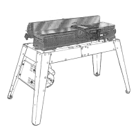
Instructions for mounting the jointer-planer unit onto the assembled leg set.
Procedure to check blade alignment and tighten setscrews for proper operation.
Steps for attaching the sliding guard to the fence for protection.
Guide for installing the motor and associated belt guards.
Verify motor rotation direction again, ensuring it's counterclockwise when viewed from the pulley.
Steps for securely attaching the motor to the machine's base.
Instructions for installing the belt guard covering the jointer and motor pulleys.
Explains how to use the handwheel to adjust the depth of cut.
How to position, lock, and adjust the fence for various operations.
Details how to read and adjust the fence tilt scale for accurate angles.
Instructions for ensuring the cutter guard is in place and functioning correctly.
Importance of keeping the infeed table parallel to the outfeed table and how to check.
Operation of the safety switch, including the key lock feature.
Proper techniques for feeding material through the jointer-planer for best results.
Guidance on using hold-down/push blocks for safe and effective jointing or planing.
How to adjust the fence and perform bevel cuts using the jointer-planer.
Step-by-step guide for safely removing and installing new cutter blades.
Instructions on how to properly install the cutter guard spring.
Methods for honing and sharpening jointer-planer blades for optimal performance.
Visual representation of the tool's electrical connections.
Guidance on which parts require periodic oiling and lubrication.
A chart detailing common problems, their causes, and recommended solutions.
List of optional accessories available for the jointer-planer.
Exploded view and parts list for the jointer-planer legs assembly.
Exploded view of the main jointer-planer components.
Detailed list of parts shown in Figure 2 for the jointer-planer.
Exploded view and parts list specific to the infeed table assembly.
Parts list and diagram for the fence assembly.
Parts list and diagram for the switch box assembly.
Instructions on how to order replacement parts and service for the jointer-planer.
| Type | Table Saw |
|---|---|
| Model Number | 113.20680 |
| Motor Power | 1 HP |
| Blade Diameter | 10 inches |
| Arbor Size | 5/8 inch |
| Max Cut Depth at 90° | 3 inches |
| Motor | 120V, Single-Phase |
| Rip Capacity | 24 inches |