Connect one learl iD rinq
To
3.2 chm
voice
coil
Iip
- No Connection
Conn.
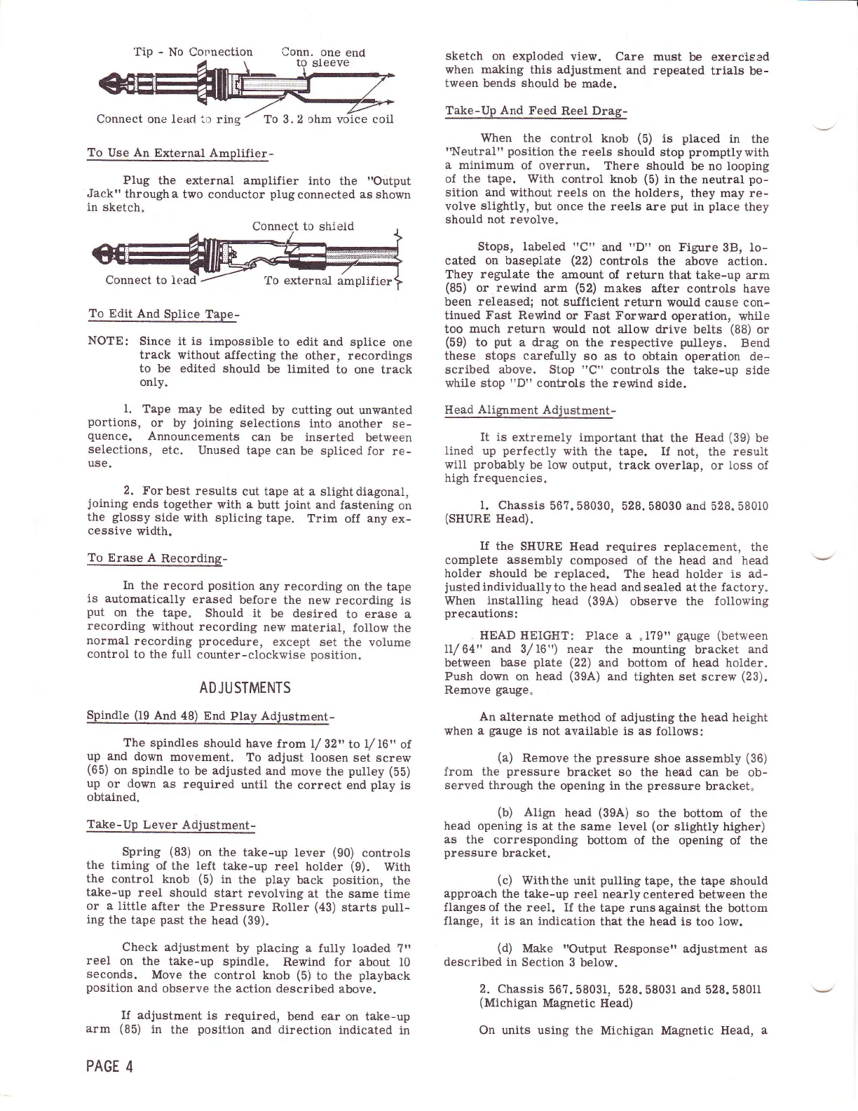
To
Use An External
Amplifier-
Plug
the external amplifier
into
the
ilOutput
Jack"
through a
two conductor
plug
connected as shown
in sketch.
To Edit
And
Splice
Tape-
NOTEI
Since it is impossible
to edit and splice
one
track
without affecting
the
othgr, recordings
to
be
edited
should
be limited
to
one
track
onlY.
1.
Tape
may
be edited
by cutting
out unwanted
portions,
or by
joining
selections
into
another se-
quence.
Announcements
can be inserted
between
selections,
etc.
Unused
tape can
be spliced for
re-
use.
2.
Forbest
results
cut tape at a
slightdiagonal,
joining
ends
together
with a
butt
joint
and
fastening
on
the
glossy
side
with splicing
tape.
Trim off any ex-
cessive
width.
To
Erase A
Recording-
In
the record
position
any
recording
on the
tape
is
automatically
erased
before
the new recording
is
put
on the
tape"
Should
.it
be desired
to erase a
recording
without
recording
new
material,
follow
the
normal
recording
procedure,
except
set
the volume
control
to the full
counter-clockwise
position.
ADJUSTMENTS
Spindle
(19
And 48)
End
Play
Adjustment-
The splndles
should have
from l/
321, to
/16'r
of
up and
down
movement.
To
adjust
loosen
set screw
(65)
on
spindle
to
be
adjusted
and
move
the
pulley
(5b)
up
or down as
required
until the
correct
end
play
is
obtained.
Take-Up
Lever
Adjustment-
Spring
(83)
on the
take-up lever
(90)
controls
the
timing
of the left
take-up
reel holder
(9).
With
the
control knob
(5)
in
the
play
back
position,
the
take-up
reel should
start
revolving
at
the
same
time
or a
little
after the
Pressure
Roller
(43)
starts
pull-
ing
the tape
past
the head
(39).
Check
adjustment
by
placing
a fully
loaded ?"
reel
on the
take-up
spindle.
Rewind for about l0
seconds.
Move the
control knob
(5)
to the
playback
position
and
observe the action described
above.
If adjustment
is
required,
bend
ear
on take-up
arm
(85)
in
the
position
and direction
indicated in
PAGE
4
sketch on
exploded
view.
Care must
be exercised
when
making
this
adjustment
and repeated
trials
be-
tween
bends
should
be made.
Take-Up And
Feed
Reel
Drag-
When the
control knob
(5)
is
placed
in
the
't{eutral"
position
the reels should
stop
promptlywith
a minimum
of
overrun. There should
be
no looping
of
the tape. With
control knob
(5)
in
the neutral
po-
sition and
without reels
on the holders,
they may re-
volve
slightly,
but once the reels are
put
in
place
they
should not revolve.
Stops, labeled
rrCtt
and
"D"
on Figure
3E!,
lo*
cated on baseplate
(22)
controls
the above actlon.
They
regulate
the
amount of return that take-up
arm
(85)
or rewind
arm
(52)
makes
aJter controls have
been released;
not suJflcient return
would cause
con-
tinued
Fast
Rervind or Fast Forward
operation, while
too
much return
would not
allow drive
belts
(88)
or
(59)
to
put
a drag on the respective
pulleys.
Bend
these stops carefully
so as to obtain
operation de*
scribed above. Stop
"C"
controls the
take-up side
while stop
"D"
controls
the rewind side.
Head
Alignment
Adjustment-
It is extremely
important
that
the
llead
(39)
be
lined up
perfectly
with
the tape. If not,
the
result
will
probably
be
low
output,
track overlap, or
loss
of
high
frequencies.
l.
Chassis
567.58030,
528.58030
and
528.58010
(SHURE
Head).
If
the SIIURE
Head
requires replacement, the
complete
assembly
composed
of the head
and
head
holder should
be replaced.
The head holder is ad-
justed
individually
to the head
and
sealed at the factory.
When
installing
head
(39A)
observe the
following
precautions:
.
HEAD HEIGHT: Place a
"
l?9t'
galrge
(between
ll/64" and 31116') near
the mounting
bracket
and
between base
plate (22)
and
bottom
of
head holder.
Push
down
on head
(39A)
and
tighten set screw
(23).
Remove
gauge"
An
alternate
method
of
adjusting
the head height
when
a
gauge
is
not available is
as follows:
(a)
Remove the
pressure
shoe assembly
(36)
from the
pressure
bracket so
the head can
be
ob-
served
through
the opening in
the
pressure
bracket"
(b)
Align
head
(39A)
so
the
bottom of
the
head opening is
at
the same level
(or
slightly
higher)
as
the corresponding
bottom of the opening of the
pressure
bracket.
(c)
lViththe
unit
pulling
tape,
the tape
should
approach
the tahe-up reel
nearlycentered
between
the
flanges of the reel. If
the tape runsagainst
the bottom
flange, it is an indication
that the head is
too
low.
(d)
Make
"Output
Responserr adjustment
as
described in Section
3
below.
2.
Chassis
567.58031,
528.5803f
and
528.58011
(Michigan
Magnetic
llead)
On units using
the Michigan Magnetic Head,
a
Connect to shield
To
external
amplifier
 Loading...