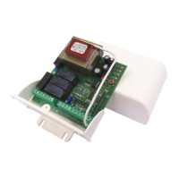
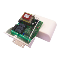
Electronic Control Unit LRX
2215
Electronic control unit for the automation of rolling shutters and
sun blinds, with optional Wind sensor connection and
keypad/radio control operation, for individual and centralised
control.
- Mod. LG 2215 : Without radio receiver
- Mod. LRS 2215 : 433,92 MHz
- Mod. LRS 2215 SET: “Narrow Band” 433.92 MHz
- Mod. LRH 2215 : “Narrow Band” 868.3 MHz
TECHNICAL DATA
- Power supply: 230 V~ 50/60 Hz 600 W max.
- Motor output: 230 V~ 500 W Max.
- Operating temperature: -1055°C
- Radio receiver: see model
- Compatible radio controls: 12-18 Bit or Rolling Code
- N° of codes which may be stored: Max. 6
- N° of Wireless Wind Sensors which may be stored: Max. 3
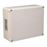
- Packaging dimensions: 110 x 121 x 47 mm.
- Container: ABS UL94V-0 ( IP54 )
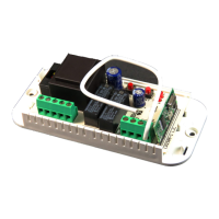
CONNECTION OF CN1 TERMINAL BOARD
1: 230 V line input (Phase).
2: 230 V line input (Neutral).
3: Upward movement motor output.
4: Shared motor output.
5: Downward movement motor output.
CONNECTION OF CN2 TERMINAL BOARD
1: Wind sensor input “W”.
2: T1 local upward movement button input (NA).
3: Shared GND Signal input.
4: T2 local downward movement button input (NA).
5: T3 general upward movement button input (NA).
6: Shared GND Signal input.
7: T4 general downward movement button input (NA).
8: Earth antenna input.
9: Antenna hot pole input.
INITIAL OPERATING CONDITION
The equipment can operate using the T1 (Up) and T2 (Down)
local command buttons, the T3 (Up) and T4 (Down) general
command buttons, and in conjunction with one or more radio
controls. There is no radio control code stored in the default
factory setting.
OPERATIONAL DATA:
T1 – T2 Local command buttons operation:
The following type of operation is obtained by connecting the
local command buttons (normally open) for movement activa-
tion to the low voltage inputs T1 – T2:
T1 controls upward movement until the motor running time has
elapsed and T2 controls downward movement. If a command is
sent in the same direction before the motor running time has
elapsed, the control unit will stop movement; if a command is
sent in the opposite direction before the motor running time has
elapsed, the control unit will invert the direction of the motor.
T3 – T4 General command buttons operation:
The following type of operation is obtained by connecting the
general command buttons (normally open) for movement activ-
ation to the low voltage inputs T3 – T4:
T3 controls upward movement until the motor running time has
elapsed and T4 controls downward movement. If a command is
sent in the same direction before the motor running time has
elapsed, the control unit will ignore the command; if a com-
mand is sent in the opposite direction before the motor running
time has elapsed, the control unit will invert the direction of the
motor.
OPERATION USING DIFFERENT MODELS OF RADIO CONTROL
Different models of radio control may be programmed: by stor-
ing one code (1 button) a cyclic step by step operation (Up -
Stop - Down) is achieved, and by storing two different codes (2
buttons) separate commands are created, one for upward
movement and one for downward movement. Storing a BeFree
series radio control (3 buttons) produces three separate com-
mands: the first button is used for upward movement, the
second for Stop and the third for downward movement.
Operation using a 1-button radio control:
The following type of operation is obtained using a radio control
with a single button: the first press controls the upward move-
ment of the shutter until the motor timer stops. The second
press controls the downward movement of the shutter. If the
button is pressed before the motor stops running, the control
unit will stop the shutter moving and the button will need to be
pressed again to reactivate the motor in the opposite direction.
Operation using a 2-button radio control:
The following type of operation is obtained using a radio control
with 2 buttons: the first button (“Up”, corresponding to upward
movement) controls upward movement until the motor stops
running and the second button (“Down”, corresponding to
downward movement) controls the downward movement of the
shutter. If the upward movement is interrupted with another
“Up” command, the motor will continue to run in its upward
movement direction. If, however, the movement is interrupted
with a “Down” command, the control unit will stop the motor.
The procedure remains the same for the downward movement
phase.
Operation using a 3-button radio control (BeFree x1):
The following type of operation is obtained using the BeFree x1
radio control: the (Up) button controls upward movement until
the end of the motor running time, the (Stop) button causes all
movement to stop and the (Down) button controls downward
movement. If a Stop command is sent during upward or down-
ward movement, the control unit causes this movement to stop.
If a command that is in the opposite direction to the current
1 Rev. 1.1 03/12/10
GB