III Internal Adjustments
Varying the output voltage adjustment of the Model 382 requires the technician to have a stable DC
power supply variable from at least 20 VDC to 30 VDC.
To access the adjustment, turn the unit upside down and remove the base plate by unscrewing the 4
securing screws in its corners. (See mechanical drawing of baseplate on page 6)
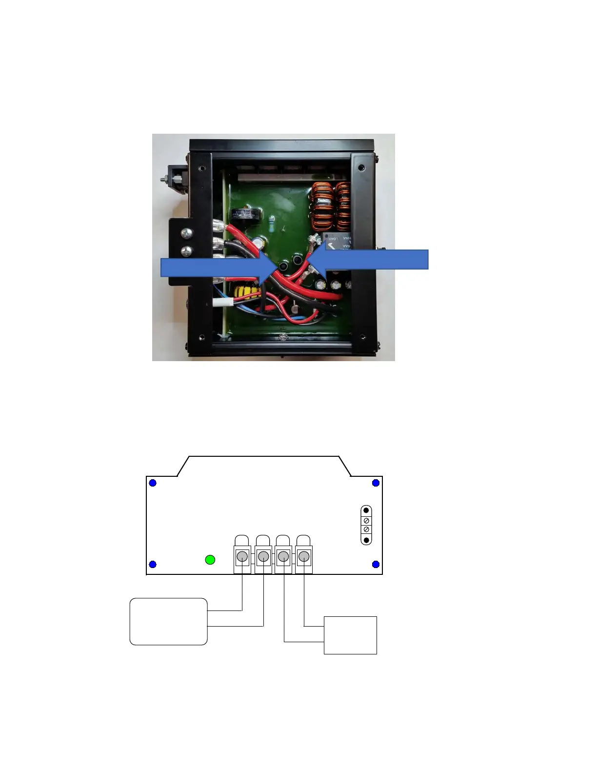
Orient the converter upside down and horizontally with the connection panel to the left as shown in
figure #3.
There are two pots as shown in Figure #3. The Current limit adjust should not be touched unless the user
has a power source which can supply and a suitable load which can draw the current at which the supply
is to be limited.
3.1) Voltage Adjustment
a) Hook up the unit to be adjusted as shown in Figure #4 under no load conditions:
Activity
Light
TBA
Input
22-60 VDC
TBB
1 2
3
4
Input
Ground
Output
Ground
Output
13.6 VDC
1
2
Power Supply
+24V
Ret
DVM
+12 V
Ret
Figure #4
b) Make sure terminals 1 & 2 on TBA are tied together and that the power supply is turned off. Set the
Digital Volt Meter to the appropriate scale to read 12 VDC to two decimals.
Page 3