III Internal Adjustments
Varying the adjustments of the Model 384 require the technician to have a stable DC power supply
variable from at least 20 VDC to 30 VDC.
To access the adjustment, turn the unit upside down and remove the base plate by unscrewing the 4
securing screws in its corners. (See drawing on page #5)
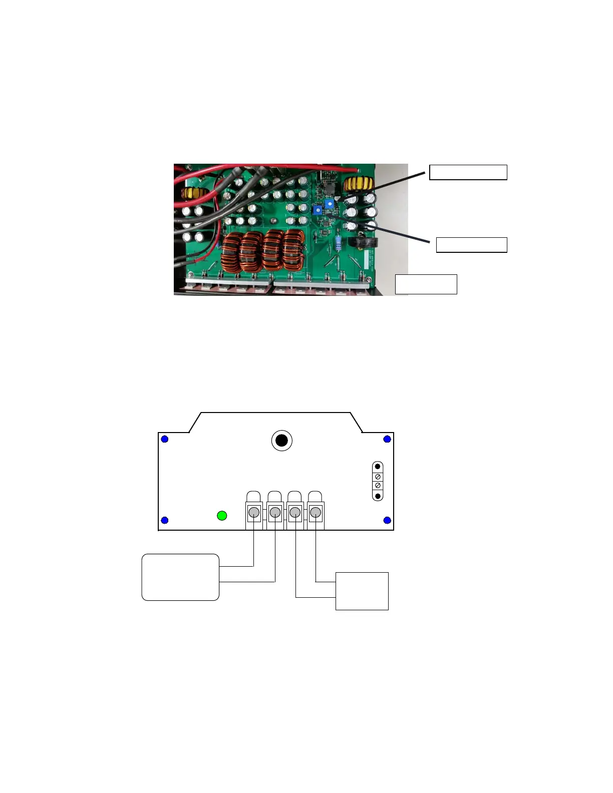
Orient the converter upside down and horizontally with the connection panel to the left as shown in
figure #4.
Two potentiometers can be noticed. The voltage adjustment pot should be used for the procedure in
(3.1). The current limit adjust potentiometer is for power limiting purposes only and intended for
technical personnel only.
3.1) Voltage Adjustment
a) Hook up the unit to be adjusted as shown in Figure #5 under no load conditions:
Activity
Light
TBA
Input
22-60 VDC
TBB
1 2
3
4
Input
Ground
Output
Ground
Output
13.6 VDC
1
2
Power Supply
+24V
Ret
DVM
+12 V
Ret
Figure #5
40
Circuit Breaker
b) Make sure terminals 1 & 2 on TBA are tied together and that the Power supply is turned off. Set the
Digital Volt Meter to the appropriate scale to read 13.60 VDC to two decimals.
c) Energize power supply and adjust its output voltage to +24 VDC. Adjust voltage adjust potentiometer
shown in figure #4 to the desired setting (between 12 VDC and 14 VDC) and observe converter voltage
output reading on DVM
d) Turn off power supply.
Page 3
Current limit adjust pot.