3/3 DES.I.101.T1.02 / 520N1301 June 2021
Secop accepts no responsibility for possible errors in catalogs, brochures, and other printed material. Secop reserves the right to alter its products without notice. This also applies to products already
on order provided that such alterations can be made without subsequential changes being necessary to specications already agreed. All trademarks in this material are the property of the respective
companies. Secop and the Secop logotype are trademarks of Secop GmbH. All rights reserved. www.secop.com
The communication port of the electronic unit
(terminal D/I and C) has two functions:
1. Communication mode (PC option):
The rst 15 seconds after power up/wake up, both
devices (compressor & PC) try to communicate.
In case a successful connection is made, the port
will stay in communication mode until next power up/
wake up.
2. Diode output mode (non PC option):
After 15 seconds with no communication link suc-
cessful established, the unit switches to diode output
mode.
No communication is possible until next power up/
wake up.
To ensure a trouble free connection using
TOOL4COOL®, the following method is recom-
mended:
Change the default TOOL4COOL® network setup
to allow TOOL4COOL® to search for the electronic
unit every 3 seconds. While TOOL4COOL® is sear-
ching, power up the electronic unit and wait for a
connection.
The following shows how to arrange this setup.
Preconditions:
The electronic unit is physically connected via the
gateway to the PC, but the power to the electronic
unit is not yet switched on.
In the example to the right, the electronic unit is con-
nected to the COM1 network.
Note:
Next to the USB connector of the gateway, there are
also two LED’s visible:
RED LED: blinks when TOOL4COOL® sends a
command to the electronic unit.
This must blink every second while TOOL4COOL®
is trying to establish a connection with the electronic
unit.
GREEN LED: blinks when the electronic unit re-
sponds to a TOOL4COOL® command.
The node address of the electronic unit must match
the command from TOOL4COOL®
(The network setting above tells TOOL4COOL® to
search for unit node address 1 every 3 sec.).
Instructions
Connecting TOOL4COOL®
to Electronic Unit 101N2130
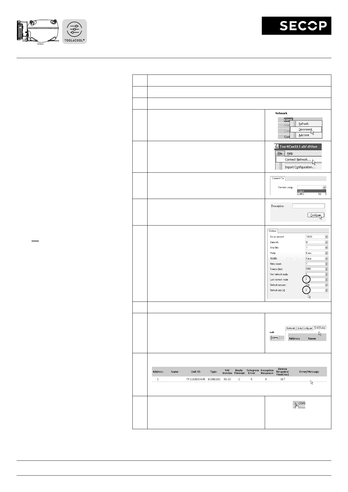
Step Description / Display
1 Do not power up the electronic unit at this stage.
2 Start TOOL4COOL®
3 In case the network is already connected, disconnect
it rst using on screen network option.
4 Wait a few seconds, then select Connect Network
(below the File menu).
5 Select the correct port, in this example COM1 is used.
6 Cick Congure.
7 Change Last network node address to 1 and
change Refresh rate to 3.
Leave the other settings at their default value and
click OK twice.
Now TOOL4COOL® will only look for an electronic
unit with address 1, but every 3 seconds. This will
ensure that the connection is established within the 15
second time limit after powering up the unit.
Leave all other options unchanged.
8 Power up the electronic unit
9 The rst time the unit is connected, TOOL4COOL®
needs to obtain the parameter le from the unit before
a connection is shown by the red arrow. Allow a few
minutes for this task to complete.
You also can read the current status by selecting the
network and then select the tab Unit Status.
10 Look under Error/Message
In this example, no errors or messages appear and the unit is working properly.
11
If the parameter le was already loaded into
TOOL4COOL®,
a connection should be visible in less
than 10 seconds.
A red arrow is added before the network name to
indicate that a unit is ready.
Click the red arrow to open
the menu of the electronic
unit.
 Loading...