Do you have a question about the See Water WS Series and is the answer not in the manual?
Overview of WS Series Simplex control panels for sewage, wastewater, and dewatering applications, UL Listed with a five-year warranty.
Instructions for wiring connections, conduit runs, branch circuit protection, and service conductor connection for NEMA 4X rating.
Critical safety precautions including power lockout, access panel security, and risk of death or serious injury.
Instructions for assembling mounting brackets to premium enclosures using provided hardware.
Details on pre-assembled gaskets for sealing covers/doors and notes on avoiding submersion.
Describes pump energization upon 'Stop' and 'Lead' float closure and operation until 'Stop' float opens.
Details the alarm activation with a 'High' float, triggering a beacon and buzzer.
Details on the 'Pump Exerciser' feature and selectable 'Run Time' options via DIP switches.
List of option codes (e.g., 24, 3R, AF) with their corresponding features and descriptions.
Advises turning off power before electrical checks or component replacement.
Procedure to test the alarm light and buzzer using the front panel test button.
Guidance on checking power, voltage, and fuse for the control board's power-on light.
Checking float status indicators, entanglement, and range of motion for proper operation.
Details the five-year warranty against defects, valid when installed per instructions.
Outlines conditions voiding warranty and limitations on manufacturer liability for installation issues.
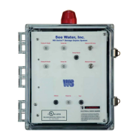
The WS Series® Simplex Control Panel, manufactured by See Water, Inc., is a robust and reliable solution designed for controlling pumps in various applications, including sewage, wastewater, and dewatering. These panels are UL Listed for both the United States and Canada, ensuring adherence to high safety and quality standards, and come with a five-year warranty, reflecting the manufacturer's confidence in their durability and performance.
The primary function of the WS Series® Simplex Control Panel is to automate the operation of a single pump based on liquid levels, preventing overflows or dry-running conditions. The system utilizes multiple floats to monitor liquid levels and trigger specific actions.
The core of its operation revolves around a sequence initiated by float contacts. When the 'Stop' and 'Lead' float contacts close, the control panel energizes the pump, causing it to run. A pump run light on the panel illuminates to indicate this active state. The pump continues to operate until the 'Stop' float opens, signaling that the liquid level has dropped to the desired minimum. This ensures efficient dewatering or sewage transfer while preventing the pump from running unnecessarily.
In scenarios where the liquid level continues to rise despite the pump running, a 'High' float is activated. This triggers an alarm condition, which is audibly indicated by an 85-decibel buzzer located 10 feet away and visually by a 360-degree visible beacon. This immediate and prominent alert system ensures that operators are promptly notified of potential issues, allowing for timely intervention to prevent overflows or system failures.
The control panel is designed to manage a wide range of pump sizes, as indicated by the various models (WS3P-TP-3001 through WS3P-TP-3014) which correspond to different Full Load Amperage (FLA) ranges, from 1.0-1.6 FLA up to 65.0-115.0 FLA. This versatility makes the WS Series® suitable for a broad spectrum of applications with varying pump requirements.
The WS Series® Simplex Control Panel offers several features that enhance its usability and adaptability in different environments.
Enclosure and Installation: The panel comes in a NEMA 4X rated enclosure, signifying its high level of protection against environmental factors such as dust, dirt, rain, sleet, snow, and even hose-directed water. This rating also indicates corrosion resistance, making it suitable for harsh industrial or outdoor settings. For installation, mounting brackets and a screw pack are provided. The brackets can be attached to the enclosure either horizontally or vertically using 1/4"-20 x 0.5 SS, countersunk phillips drive screws, or other acceptable fastening techniques. The enclosure's covers/doors are equipped with a pre-assembled gasket to ensure a tight seal against the base, further contributing to its NEMA 4X rating. It is crucial to note that the control panel should not be mounted in a location subject to submersion.
Wiring and Connections: To maintain the NEMA 4X rating, all wiring connections must be made with seal-tight cable grips or conduit connections. Users are instructed to run pump cables and float cables through conduit and make field connections as shown on the provided wiring schematic. Similarly, the power line conductor should be run through conduit and wired to terminals as per the schematic. Branch circuit protection must be provided by the installer. The panel circuit breakers are typically closed upon installation.
Float Management: Proper float mounting is critical for accurate level sensing. Floats must be installed at the correct levels and have a free range of motion, ensuring they do not touch each other or other equipment, which could lead to erroneous readings or operational issues.
Power Supply: The panel is designed to connect to service conductors of 208V, 240V, or 480V, depending on the specific model and application requirements.
Remote Monitoring: For enhanced operational oversight, the panel includes remote monitoring dry contacts. These are normally open contacts for high level, pump run, and pump fault conditions. These contacts allow for integration with external monitoring systems, providing real-time status updates and alerts to a central control room or remote operators. Users should refer to the wiring schematic for proper termination of these contacts.
Optional Features: The WS Series® Simplex Control Panel can be customized with a variety of optional features to meet specific application needs:
The WS Series® Simplex Control Panel is designed with ease of maintenance and troubleshooting in mind, ensuring minimal downtime and prolonged operational life.
Safety First: Before performing any electrical checks or attempting to replace components, it is imperative to turn off all branch circuits supplying power to the main control panel. This crucial safety measure prevents electrical shock and ensures the safety of maintenance personnel.
Alarm Circuit Troubleshooting: The panel includes a test button on the front panel specifically for checking the alarm light and buzzer. If either the light or buzzer fails to activate during the test, they should be replaced with the same type. This simple test allows for quick verification of the alarm system's functionality.
Control Board and Fuse Diagnostics: If the power on light on the front panel is not illuminating, troubleshooting steps involve checking the voltage at terminals TS1-1 and TS1-2 using a voltage meter. A reading of 120VAC indicates that power is present. If voltage is present, the next step is to check the fuse in the fuse box. A blown fuse should be replaced with the same type. The dry contacts on the control board are rated for 0-60 VAC or VDC, with a maximum current of 1 amp.
Float Inspection: The control board features individual float status indicators that illuminate when the floats are in the closed position. This visual feedback helps in quickly identifying which floats are active or stuck. During maintenance, it is important to check the floats for any entanglement or obstructions that might impede their full range of motion. Damaged floats should be replaced promptly to ensure accurate level sensing and reliable pump operation.
Gasket Maintenance: The covers/doors of the enclosure have a pre-assembled gasket to seal against the base. Regular inspection of this gasket for wear and tear is recommended to maintain the NEMA 4X rating and protect internal components from environmental ingress.
Warranty Support: See Water, Inc. provides a five-year warranty against defects in material and workmanship from the date of purchase. This warranty is valid when the product is installed in compliance with the manufacturer's instructions. In the event of a defect, the manufacturer's obligation is limited to the repair or replacement of defective parts, provided the product is returned to the factory, postage prepaid, with proof of original purchase. This warranty support underscores the manufacturer's commitment to product quality and customer satisfaction. It is important to note that improper installation, alterations, or additions to the product will void the warranty, as these actions can lead to personal injury or equipment malfunction.
| Series | WS Series |
|---|---|
| Display | LCD |
| Protection Rating | IP65 |
| Operating Temperature | -10°C to 50°C |
| Communication Interface | RS485 |