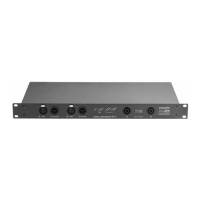
Fig. 16 Two waves of equal amplitude, frequency and phase add up to a wave of twice the amplitude (a).
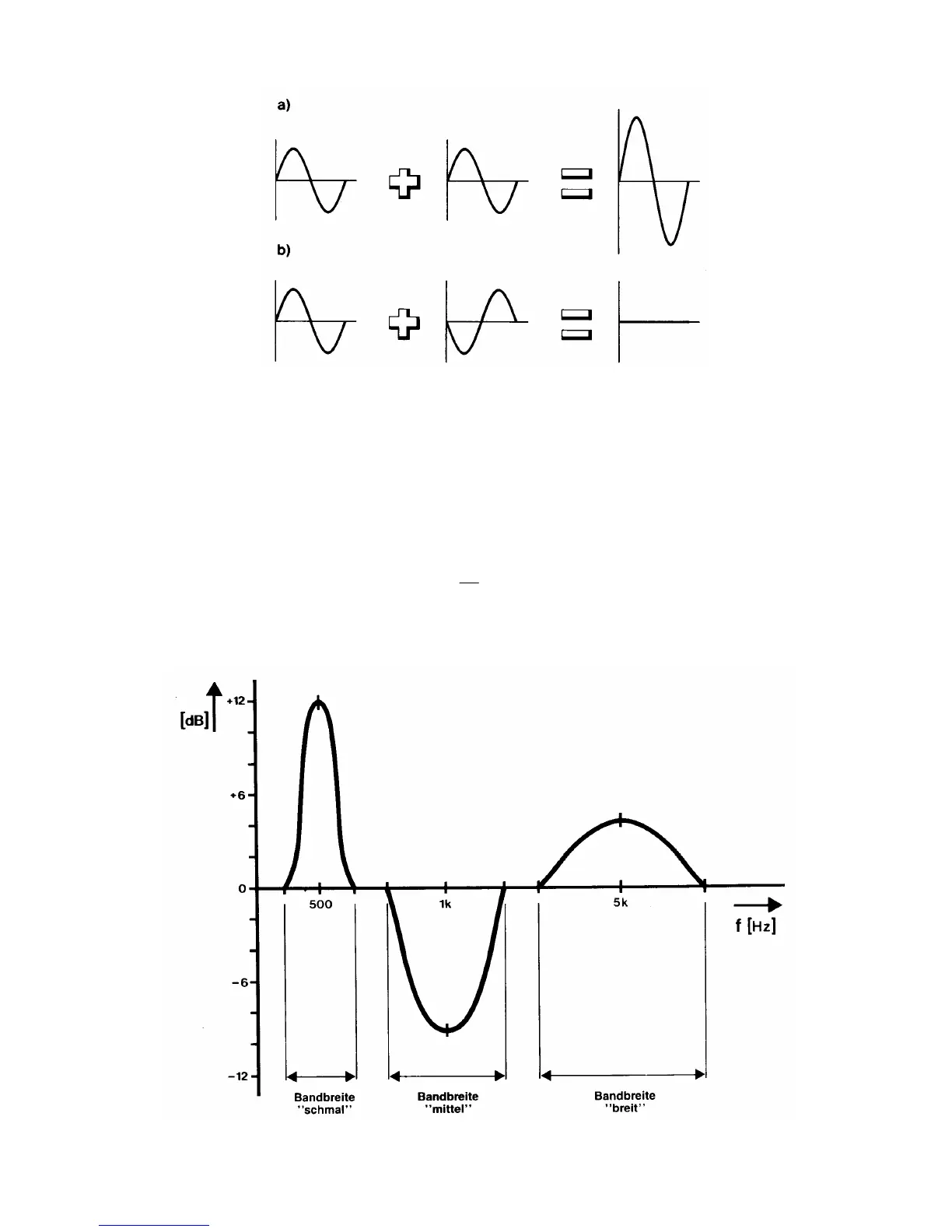
• Filter Q: The quality factor (Q) of a resonant filter is a measure for the sharpness of the
resonance peak that can be realized with this circuit. Every equalizer contains a number of
electric resonant filters. A equalizer with a low Q will affect the frequencies in the vicinity of the
resonance peak stronger than one with a high Q. So, if you want to control only a very narrow
frequency band you have to choose a very high Q filter. However, in many applications it is
desired to affect a wider range (for example a broad bass boost between 50 and 150 Hz in a PA
system), which can be achieved with a low filter Q (see fig. 17).
The filter Q for electrical resonant circuits can be expressed as:
Q
f
=
0
B = fu-fl: Bandwidth. fu is the upper 3 dB point, fl is the lower 3 dB point.
fo: Center frequency.
Fig. 17 Filter Q and Bandwidth.