Do you have a question about the Seeing Machines Guardian and is the answer not in the manual?
Covers preface and compliance certificates for the Guardian Gen 2 system.
Provides an introduction to the Guardian Generation 2 system, its purpose, and overview.
Details the procedures and requirements for installing the Guardian Gen 2 system.
Outlines the steps for servicing and maintaining the Guardian Gen 2 system.
Access to articles, guides, and fixes for known issues related to the Guardian system.
A checklist to ensure all steps are completed during the installation process.
Provides video resources for understanding and performing tasks related to the Guardian system.
Details compliance with FCC Part 15 regulations for digital emissions.
States compliance with FCC RF radiation exposure limits for uncontrolled environments.
States compliance with IC RSS-102 radiation exposure limits for uncontrolled environments.
Framework for managing risks and hazards, prioritizing elimination over PPE.
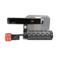
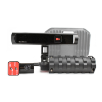
Details the Controller Unit, its mounting pan, and associated fasteners for installation.
Describes the ICS module, its cable, mounting arm, and related components.
Details Hard and Soft mount options for the ICS, and specific fasteners like self-tapping screws.
Details the Forward Facing Camera (FFC), Vibration Motor, and Multi-Function Cable (MFC).
Describes 3/4G and GPS antennas, and associated mounting hardware like clamps and VHB tape.
Details the power cable, fuse holder, fuse, and various terminals for electrical connections.
Specifies crimp terminals, zip ties, and blanking grommets for wiring management.
The Security Torx 20 (T20) key is essential for various installation adjustments and securing components.
Business card providing contact details for 24/7 support services.
Information card regarding the USB Recovery Dongle for system software updates.
The USB Recovery Dongle (min 4GB) is used for system software installation and recovery.
An adapter to connect the laptop's USB port to the Guardian Controller's Ethernet port.
Manual for the USB to Ethernet Adapter, software usage may vary by OS.
An Ethernet cable used for connecting the laptop to the Guardian Controller.
The 1.5mm Allen Key is used to adjust and lock the FFC camera screw.
A laptop is required for installation and maintenance functions, with specific OS support.
Used for determining camera Pitch and Yaw settings using degrees.
A comprehensive bit and socket set for various installation tasks, including Phillips, Pozidriv, Torx, and Hex bits.
A set of ratchet spanners in various metric sizes for tightening fasteners.
Vice grips are used for securely holding components during installation.
Various drill bit sizes (2, 4, 6, 7mm) for creating holes as needed.
A 25mm (1 inch) hole saw for making precise openings for cables or components.
A multimeter and leads are used for electrical testing and verification.
Tools for cutting wires and flush trimming excess material.
Tools for stripping insulation from wires to make electrical connections.
Specialized crimpers for making secure electrical connections on automotive wiring.
A torch or head torch for illumination in poorly lit areas during installation.
Scissors for cutting various materials as needed during installation.
A utility knife, to be used based on site-specific requirements for cutting or trimming.
A cordless drill for driving screws and making holes during installation.
A cordless impact driver for faster and more powerful screw driving.
A brush for cleaning dust or debris from surfaces or components.
Electrical tape for insulating and securing wires and connections.
Instructions for setting up Windows-based laptops to communicate with the Guardian Controller via Ethernet.
Guidelines for taking and archiving photos of the installation for evidence and record-keeping.
Procedures for programming and using the USB Recovery Dongle for system software updates.
Steps to download the necessary software for the USB Recovery Dongle from the TCP.
Instructions on how to program the USB Recovery Dongle with the Guardian Gen 2 software.
Pre-arrival checks including SIM card status, arrival time, and site access.
Procedure for collecting and verifying Nano SIM cards required for system installation.
Checking job cards for requests and ensuring installer kit items are available.
Verifying configuration files and checking package contents for all required parts.
Filling in job cards and taking pre-installation photos for insurance.
Ensuring site safety rules, PPE, and inductions are completed before installation.
Completing the physical installation of the Guardian system components into the vehicle.
Following IVS Wizard steps, confirming successful completion and ICS positioning.
Taking photos of each installed component as evidence of a quality installation.
Instructions on when and how to contact support for errors encountered during installation.
Running the recovery process, connecting the laptop, and proceeding through the IVS Wizard.
Scanning or photographing paperwork for records and completing/submitting the Job Card.
Archiving photos for recall, allowing Wi-Fi upload if using cloud storage.
Critical safety instructions regarding airbag locations and avoiding interference during installation.
Using and filling the installation checklist, including locating serial numbers.
Detailed instructions for installing the Nano SIM card into the Controller Unit.
Details the Controller Unit, its mounting pan, and fasteners for installation.
Considerations for selecting the most suitable mounting location for the Controller Unit.
Specifies mounting location and distance for the In-Cab Sensor (ICS) for optimal face tracking.
Details mounting arm flexibility and Hard/Soft mount options for the ICS, including warnings.
Instructions for installing the ICS using the Hard Mount method.
Instructions for installing the ICS using the Soft Mount method, with associated risks.
Guidelines for mounting the FFC, considering country regulations and windscreen visibility.
Describes mounting types for FFC based on vehicle bonnet presence (top or bottom windscreen).
Procedures for adjusting and locking the FFC camera position using an Allen key.
Specifies mounting location for 3/4G antenna for clear line of sight to the sky, avoiding metal.
Details mounting the 3/4G antenna using adhesive tape.
Specifies mounting location for GPS antenna for clear line of sight to the sky, avoiding metal.
Describes mounting the GPS antenna to face the sky using adhesive pads.
Specifies mounting location for Vibration Motor on the driver's seat, avoiding interference.
Details various mounting methods for the Vibration Motor, including bar mount options.
Routing the power cable and connecting fuse holders at the fuse box.
Details connection methods, vehicle isolation, and wiring identification.
Steps to identify and verify a suitable ground source for the system's black wire.
Steps to identify and verify ignition (yellow) and battery (red) wire sources.
Describes the MFC's connections to various system components and the Controller.
Details how the main connector and six-pin connector plug into the Controller and Vibration Motor.
Ensuring sufficient cable length and slack, and routing cables for easy access to the Controller.
Using cable relief systems to minimize pull on cables and facilitate Controller cover removal.
Procedures for uploading the latest software using a USB Recovery Dongle.
Verifying system, GPS, and network time, and manually configuring UTC if necessary.
Configuring external peripherals like FFC and Mix Telematics.
Configuring third-party signals and adjusting ICS camera rotation for optimal placement.
Calibrating camera Pitch and Yaw using auto or manual methods and creating test events.
Verifying authentication status, reviewing installation, and downloading reports.
Completing system checks on the Dashboard page to ensure optimal system performance.
Provides contact details for the 24/7 Support Center and TCP access.
Steps for activating a vehicle in Guardian Live by contacting 24/7 Support with checklist details.
Tucking cables into relief, sliding cover plates, and securing the Controller.
A checklist of final checks to ensure the system is installed correctly and completely.
| Features | Real-time detection of fatigue, microsleeps, distraction, and drowsiness |
|---|---|
| Applications | Commercial vehicles, mining equipment, fleet management, heavy machinery |
| Monitoring Capability | Driver's eyes, head position, and facial expressions to detect fatigue and distraction |
| Alert System | Audible and visual alerts for fatigue and distraction events |
| Connectivity | 4G/LTE, Wi-Fi, GPS |
| Power Supply | 12/24V DC |
| Storage Temperature | -40°C to +85°C |
| Dimensions | Varies depending on the specific Guardian model |
| Weight | Varies depending on the specific Guardian model |
| Type | Driver Monitoring System (DMS) |