14 TD_MRI1_06.05_GB
4.5 Earth-fault directional feature
(ER/XR-relay type)
A built-in earth-fault directional element is available for
applications to power networks with isolated or with
arc suppressing coil compensated neutral point.
For earth-fault direction detection it is mainly the ques-
tion to evaluate the power flow direction in zero se-
quence system. Both the residual voltage and neutral
(residual) current on the protected line are evaluated to
ensure a correct direction decision.
In isolated or compensated systems, measurement of
reactive or active power is decisive for earth-fault de-
tection. It is therefore necessary to set the ER/XR-relay
type to measure according to sin ϕ or cos ϕ methods,
depending on the neutral-point connection method.
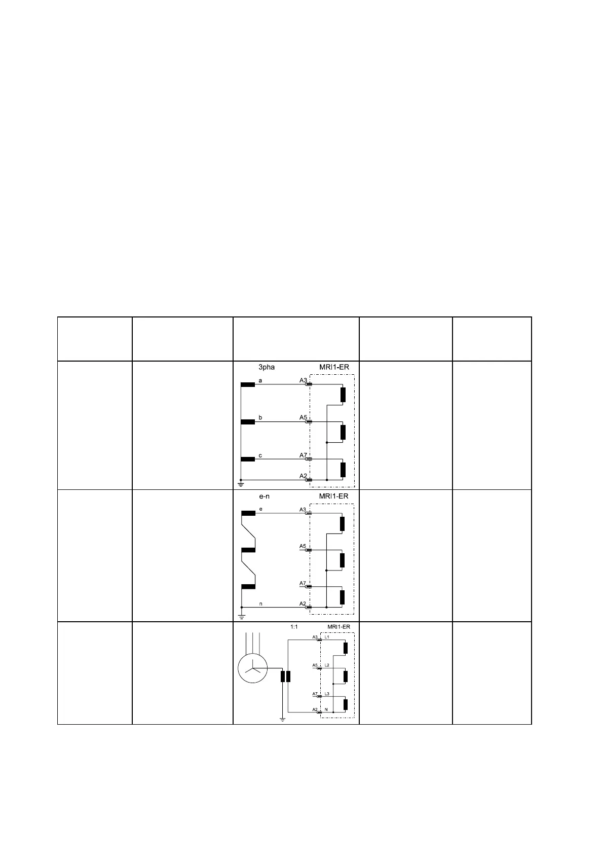
The residual voltage U
E
required for determining earth
fault direction can be measured in three different
ways, depending on the voltage transformer connec-
tions.
(refer to Table 4.1:)Total current can be measured by
connecting the unit either to a ring core C.T. or to cur-
rent transformers in a Holmgreen circuit. However,
maximum sensitivity is achieved if the MRl1 protective
device is connected to a ring core C. T. (see Figure
3.2).
The pick-up values I
E>
and I
E>>
(active or reactive cur-
rent component for cos ϕ or sin ϕ method) for ER-relay
types can be adjusted from 0.01 to 0.45 x I
N
. For re-
lay type MRI1-XR these pick-up values can be ad-
justed from 0.1 to 4.5 % I
N
.
Adjustment
possibility
Application Voltage transformer
connections
Measurd
voltage at
earth fault
Correction fac-
tor for residual
voltage
“3pha”
3-phase voltage
transformer connected
to terminals A3, A5,
A7, A2
(MRI1-IRER;
MRI1-IER;
MRI1-ER/XR)
√3 x U
N
= 3 x U
1N
K = 1 / 3
“e-n”
e-n winding
connected to
terminals A3, A2
(MRI1-IER;
MRI1-ER/XR)
U
N
= √3 x U
1N
K = 1 / √3
“1:1”
Neutral-point voltage
(= residual voltage)
terminals A3, A2
(MRI1-IER;
MRI1-ER/XR)
U
1N
= U
NE
K = 1
Table 4.1:
 Loading...